Electrical connections
6 720 802 419 (2012/06) en
35
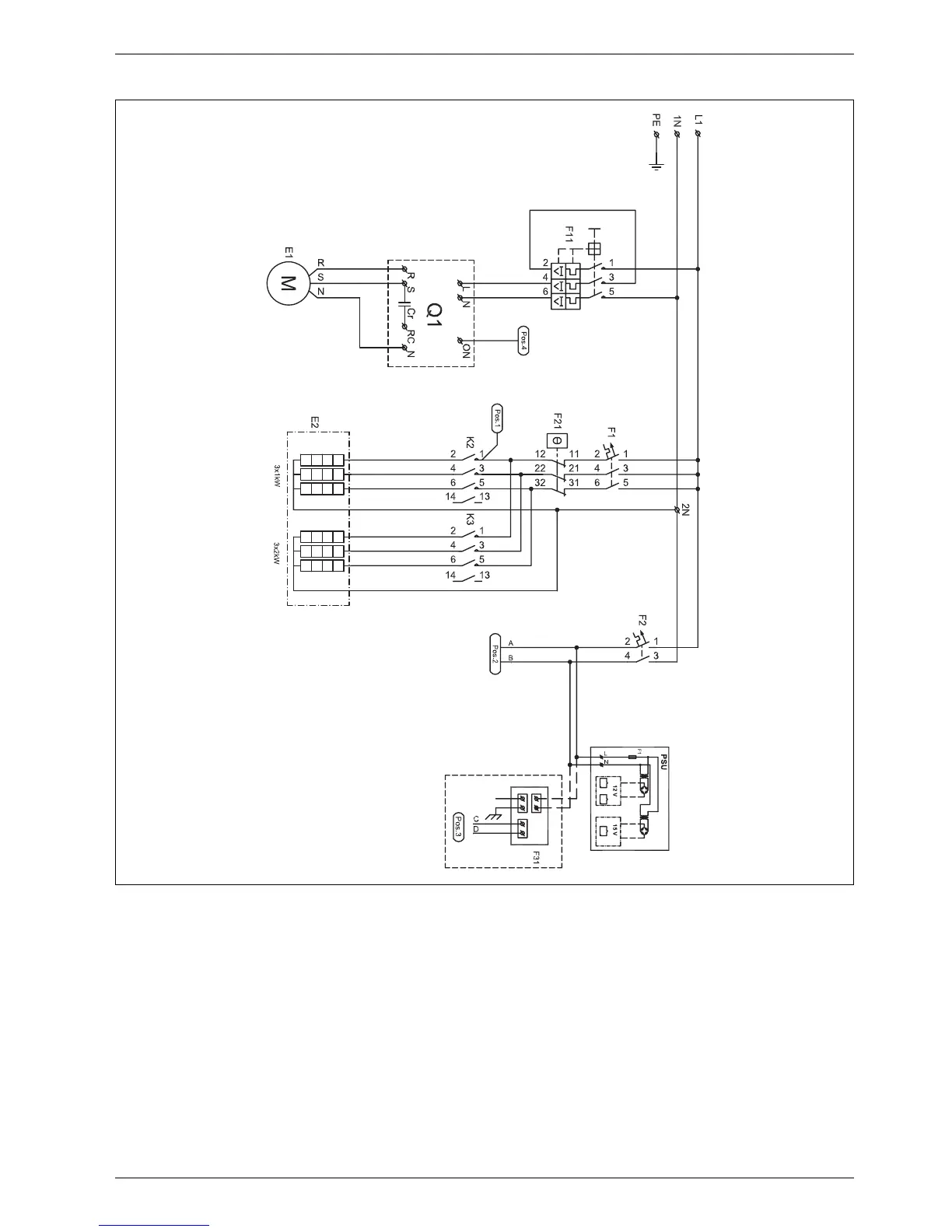
10.3.5 Internal wiring diagram
Fig. 32 Internal wiring diagram
[E1] Compressor
[E2] Electric additional heat
[F1] Miniature circuit breaker electric additional heat
[F2] Miniature circuit-breaker heat pump
[F11] Motor cut-out compressor
[F21] Power supply to overheat protection
[F31] Protective anode, C-model with stainless water heater
[K2] Contactor electric additional heat stage 1
[K3] Contactor electric additional heat stage 2
[Q1] Soft starter
[PSU] Circuit board
6 720 802 416-10.1I