J2 225 System Manual
Version 1.0 May 29, 2012
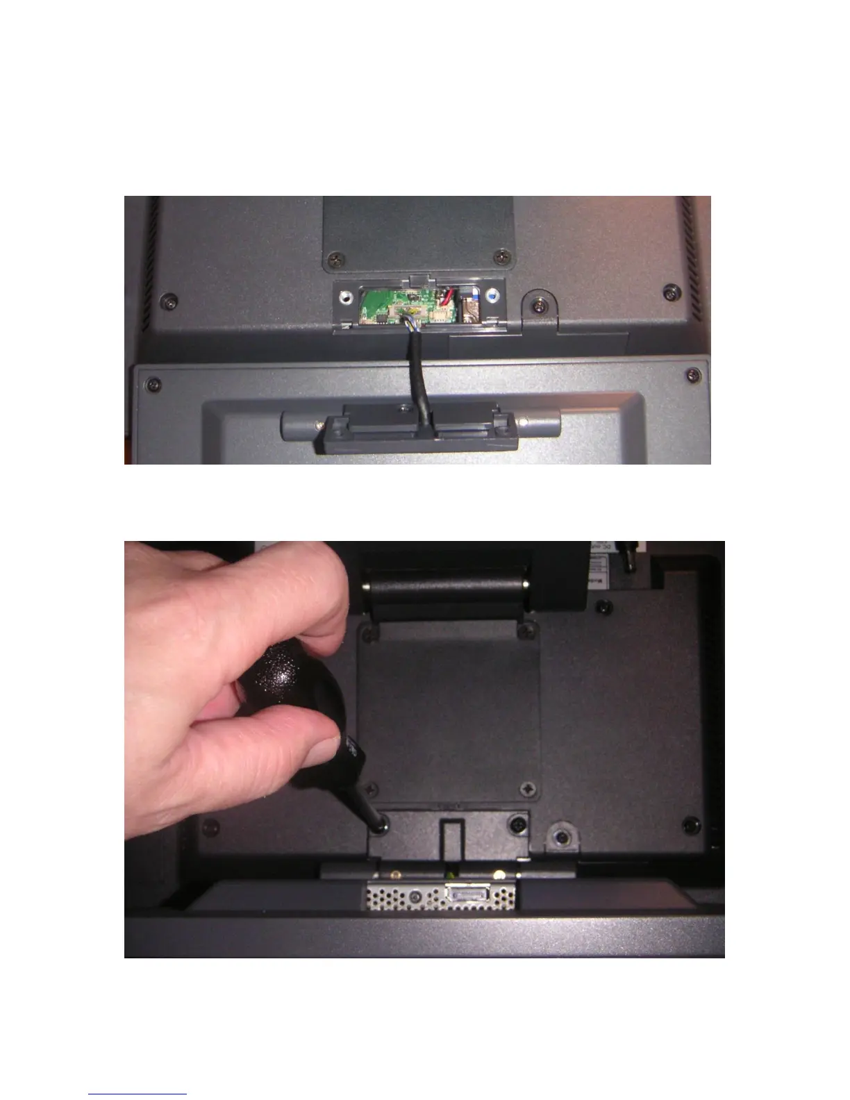
After the secondary display cover is removed, attach the 10.1” display cable to the unit.
This 20-pin cable plugs into the CN6 connector on the system board. The connector is
keyed so that it can only plug in one way. This cable provides power and video data to
the 10.1” display.
Once the cable is plugged in, feed any extra cable into the unit and attach the LCM with
the two 4mm screws provided with the display.