2-4 4247530-Rev A
SPECIFICATIONS AND GENERAL INFORMATION
2
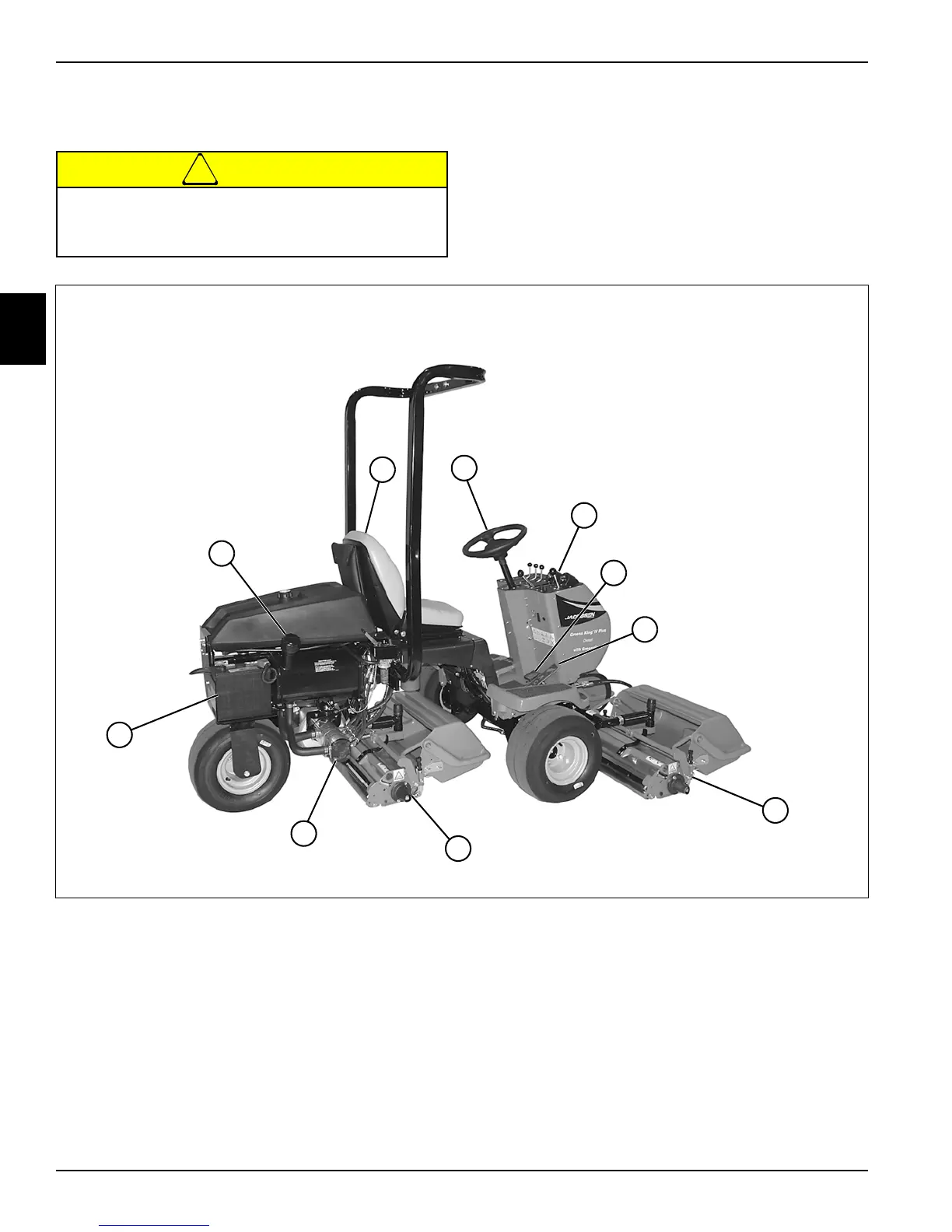
Component Location
See Figures 2-5 and 2-6.
!
CAUTION
Figure 2-5: Component Location—Right Side
Become familiar with operator controls, machine
components, and correct operating procedures
before beginning repair procedures.
1 Seat 6 Right Cutting Unit
2 Steering Wheel 7 Center Cutting Unit
3 Instrument Panel 8 Hydraulic Pump
4 Brake Pedal 9 Battery
5 Traction Pedal 10 Hydraulic Oil Tank
TN3247
1
3
2
7
8
4
9
10
5
6