Page 16
1998-2006 Edition
9. Slide the Stove into its final position while guiding the
installed vent system through the wall thimble. Refer to
Chapters III and IV (Clearances to Combustible Materials
Requirements) to ensure that the final position of the stove
adheres to all the listed requirements.
10. Check for wall thimble fit around the 4-3/4" (121mm) pipe,
adjust as necessary and secure the wall thimble pieces to the
wall using eight screws designed for your wall material type.
11. Fill any gaps between the wall thimble and the 4-3/4"
(121mm) pipe with RTV silicone.
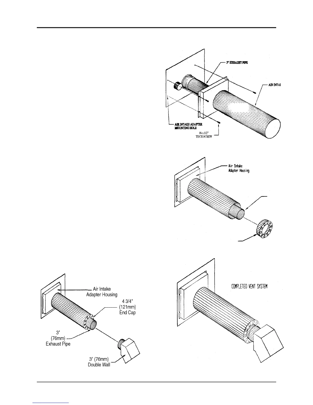
12. Slide the 4-3/4" (121mm) End Cap/Rodent Screen (part #
7) so that the sleeve fits inside the 4-3/4" (121mm) pipe and the
3" (76mm) exhaust pipe slides through the 3" hole at the center
of the End Cap. Secure the cap in place using one #8 x 1/2"
Teck Screw through the screw hole on the side of the 4-3/4"
(121mm) pipe.
13. Slide the 3" (76mm) Double Wall Rain Cap ( part # 8) over
the end of the 3" (76mm) exhaust pipe with the open end of the
cap facing downward at an angle, as shown in Figure A.
Secure the Rain Cap to the 3" (76mm) exhaust tube using three
#8 x 1/2" Teck Screws. Space the screws evenly around the 3"
(76mm) tube.
Installation of the "through the wall exhaust kit" is now complete.
Check the entire exhaust system to ensure that there are no
exhaust gas leaks.
Where passage through a wall, or partition of
combustible construction is desired, the installation
shall conform to CAN/CSA-B365 Installation Code for
Solid Fuel Burning Appliances and Equipment in
Canada.