Page 8
Aux Etats-Unis, ce chauffe-piscine doit être
installé á au moins 5 pieds (1,5 m) de la paroi
interne de la piscine à moins d’être isolé de la
piscine par une clôture, un mur ou autre barrière
permanente.
En Estados Unidos, esta bomba de calor
deberá instalarse a una distancia de al menos 5 pies
(1,5 metros) de la pared interior de la piscina; a
menos que la bomba de calentar esté separada de
la piscina mediante una valla sólida de 5 pies (1,5
metros) de altura u otra barrera permanente.
In Canadian installations, the minimum distance to
be maintained from the inside wall of the pool or spa is
3 meters (approx. 10 feet).
Pour les installations canadiennes, la distance
minimale à maintenir du mur intérieur de la piscine
ou du spa est de 3 mètres (approximativement 10
pieds).
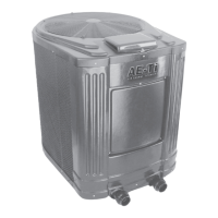
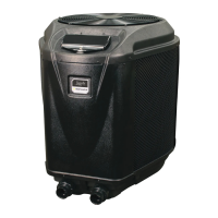
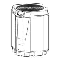
2.2.3 Equipment Pad
Place the heat pump on a flat slightly pitched
surface, such as a concrete or fabricated slab (pad). This
allows proper drainage of condensation and rain water
from the base of the unit. If possible, the pad should be
placed at the same level or slightly higher than the filter
system equipment pad.
NOTE Ensure that the pad is pitched not more than ¼
inch per foot toward the compressor end (front)
of the heat pump. Pitch slab from back to front
¼ inch per foot maximum and level from side to
side.
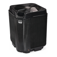
2.2.4 Condensation and Drainage
Condensation will occur from the evaporator coil
while the unit is running and drain at a steady rate,
usually three to five gallons per hour, depending upon
ambient air temperature and humidity. The more humid
the ambient conditions, the more condensation will be
produced. The bottom of the unit acts as a tray to catch
rainwater and condensation. Keep the drain hole located
on the right side of the base of the unit clear of debris.
If the heat pump is installed indoors, means of
condensate disposal must be provided. The drain hole
in the base of the heat pump is tapped to fit an optional
3/4” diameter barbed adapter, Jandy p/n R3004100 (see
Section 9, “Replacement Parts”). If using the barbed
adapter, connect a length of 3/4” tubing (5’ is included
in Jandy p/n R3004100) to the adapter, then route it
into a drain or outside the building to dispose of the
condensate. It is important to remember that no part of
the tubing or hose may be above the level of the drain
hole in the base of the heat pump.
2.2.5 Lawn Sprinklers
Keep lawn sprinkler heads from spraying on the
heat pump to prevent corrosion and damage. Use a
deflector if needed.
2.2.6 Roof Run-off
Make sure the heat pump is not located where
large amounts of water may run-off from a roof into
the unit. Sharp sloping roofs without gutters will allow
massive amounts of rain water, mixed with debris from
the roof to be forced through the unit. A gutter or down
spout may be needed to protect the heat pump.
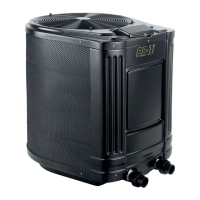
2.2.7 Installation of Anchor Clamps
In Florida, building codes require that the heat
pump be anchored to the equipment pad or platform
to withstand high wind pressures created during
hurricanes.
This heat pump is provided with anchor clamps
designed to hold the unit to the equipment pad in high
wind conditions. Installation of the anchor clamps is
recommended in all installations and are required in
Florida (reference Florida Building Code, Mechanical
Section 301.13).
To install the anchor clamps:
1. Be sure that the heat pump is in its permanent
location on the equipment pad.
2. Remove the anchor clamps from the installation
and instruction package.
NOTE: Bolts and bolt anchors are not included with
the heat pump. Jandy recommends that a
1/4” x 1½” long stainless steel Tapcon
®
type
concrete screw is used to mount the clamp
to the equipment pad. The Tapcon type
concrete screw meets Florida building code
requirements.
3. Place the clamps at the base of the heat pump in
the locations indicated in Figure 2.
NOTE: To Install the brackets on the front of the heat
pump, the front cover must be loosened enough
in order to place the bracket over the lip of the
base. Be sure to re-tighten the front jacket
panel to the heat pump.
4. Fit the hook of each clamp over the lip on the
base panel of the heat pump. The hook should
fi t between the lip of the base panel and the
evaporator coil guard (see Figure 3).