Page 9
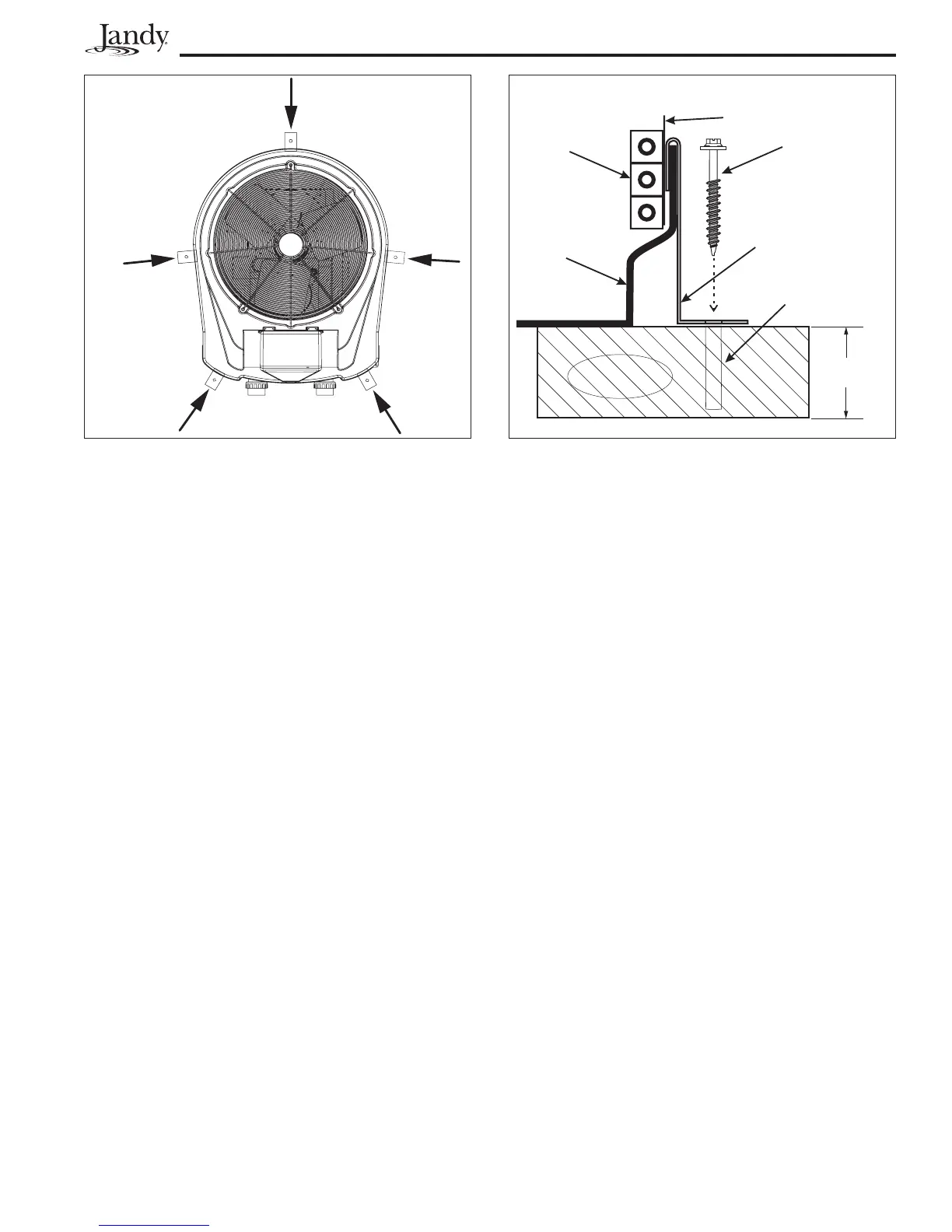
5. Mark the position of the hole in each clamp on the
equipment pad.
6. Drill a hole in the cement using a masonry drill
bit, with a diameter as determined by the concrete
anchor, at each of the marks on the equipment pad.
The hole should be approximately 1-1/2” deep.
7. Insert a bolt anchor into each of the holes. Be sure
the anchors are set completely into the holes.
8. Position the anchor clamps so that the holes in the
clamps are over the bolt anchors. Be sure that the
clamp hooks are over the lip of the heat pump base
(see Figure 3).
9. Insert an anchor bolt through each clamp into the
anchor and tighten to secure the clamp and heat
pump to the equipment pad.
Section 3. Water Connections
3.1 Plumbing Layout
Figure 4 illustrates the standard plumbing layout
with a single heat pump unit. Following the diagram
from right to left, the plumbing sequence is as follows:
Pool > Pool Pump > Filter > Heat Pump > Check
Valve > Chemical Loop > Chlorinator > Pool
NOTE For normal installations, do not install a shutoff
valve or any kind of variable restriction in the
water piping between the heat pump outlet and
the pool/spa.
Arrangement of pool system components other
than as illustrated in the preceding and following
diagrams can affect the operation of the heat pump’s
water pressure switch. Location of the heat pump above
or below the pool water surface can also affect operation
of the switch. In general, the pressure switch can be
adjusted to accommodate this effect if the heat pump
water connections are no more than five feet below the
pool water surface or no more than 11 feet above it. See
instructions for pressure switch adjustment (Section
5.6) in the heat pump start-up section of this manual for
more information. If the heat pump is installed outside
of this range, an external flow switch may need to be
installed in the plumbing upstream of the heat pump.
Call the Jandy Heat Pump Technical Service department
at (954) 970-4800 for details.
Be advised that when pool equipment is located
below the pool surface a leak can result in large scale
water loss or flooding. Jandy cannot be responsible for
such water loss or flooding or the damage caused by
either occurrence.
3.2 Water Connections at Heat Pump
Shipping plugs have been installed in the water
inlet and outlet ports of the heat pump at the factory.
Before installing any plumbing, remove the shipping
plugs. Filtered water is plumbed to the inlet, located on
the right side of the heat pump front panel. Heated water
flows through the outlet, located on the left side of the
heat pump front. Two inch unions are provided.
Plastic piping (PVC Schedule 40) should be
connected to the heat pump. The unions, provided with
the unit, accept 2” PVC pipe.
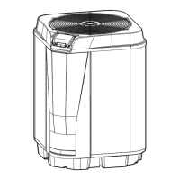
Figure 3. Anchor Clamp Installation
3" minimum
1/4" x 1-1/2"
STAINLESS STEEL
TAPCON
®
TYPE
CONCRETE SCREW
AND WASHER
(Installer Provided)
EVAPORATOR
COIL GUARD
EVAPORATOR
COIL
HEAT PUMP
PLASTIC BASE
HEAT PUMP
ANCHOR
BRACKET
3/16" DRILLED
HOLE
CONCRETE
EQUIPMENT PAD
Attach anchor
brackets to base
of heat pump
where indicated
by the arrows.
Figure 2. Anchor Clamp Positions