Page 1 1
C artridge Pool Filters - C L and C V S eries Filters
9. After the pressure gauge has stabilized, turn the
bezel ring so that the arrow next to the word
CLEAN
to clog the pressure begins to increase. When the
needle of the pressure gauge aligns with the arrow
next to the word on the bezel, it is time
an increased pressure of between 10 and 12 psi
above original starting pressure.
Section 5. Filter Disassembly and
Assembly
W A RN I N G
N E V E R a t t e m p t t o a sse m b l e ,
d i sa sse m b l e o r a d j u st t h e f i l t e r w h e n
t h e r e i s p r e ssu r i ze d a i r i n t h e syst e m .
S t a r t i n g t h e p u m p w h i l e t h e r e i s
a n y p r e ssu r i ze d a i r i n t h e syst e m
ca n ca u se t h e f i l t e r l i d t o b e b l o w n
o f f , w h i ch ca n ca u se d e a t h , se r i o u s
p e r so n a l i n j u r y o r p r o p e r t y d a m a g e .
1. Turn off the pump. Switch off the circuit breaker
to the pump motor.
2. IMPORTANT: Completely open air release valve
on top of the lter tank to release all pressure
from inside the tank and system.
4. Remove the drain plug located at the bottom of the
5. Replace the drain plug.
6. Loosen the tank clamp ring retainer and remove
the clamp ring.
straight up until it clears the cartridges on the
inside of the tank.
8. Remove the manifold assembly by lifting it off of
the outlet tube and out of the tank.
the cartridge using the instructions in Section 6.3.
10. Using new cartridges or the clean original ones,
sure that they are correctly seated on the cartridge
support on the bottom of the tank.
11. Inspect the o-ring at the top of the outlet tube for
cracks and wear marks. Replace if necessary.
squarely over the cartridges and outlet tube.
13. Inspect the tank o-ring for cracks or wear marks.
Replace if necessary. Place the o-ring back onto
15. Replace the tank clamp ring. See Section 3.4 for
clamp installation.
16. Start the pump by following the procedures
outlined in steps 2 through 7 of Section 4.1.
Section 6. Maintenance
6.1 General Maintenance
water. Rinse off with a hose. Do not use solvents
to clean the lter, solvents will damage the plastic
components of the lter.
2. Check pressure during operation at least once a
week.
3. Remove any debris from the skimmer basket and
develop, turn off the pump and call a qualied
pool service technician.
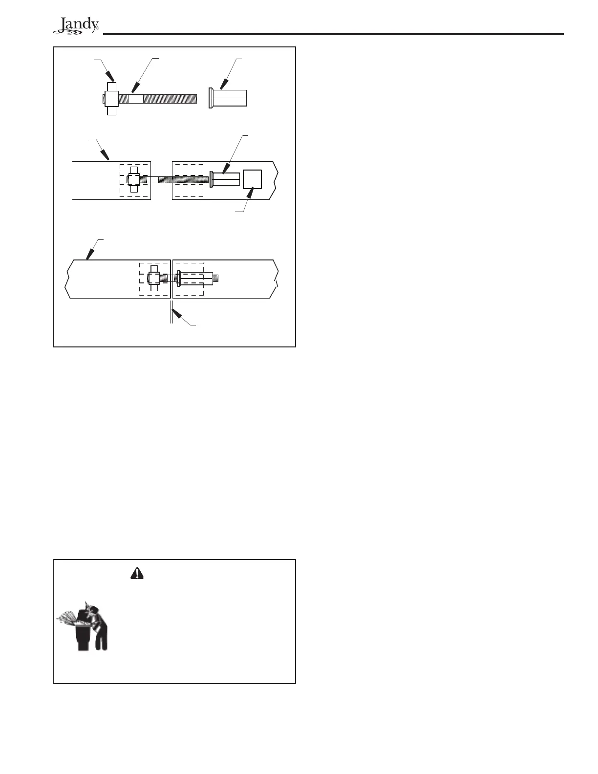
Figure 1 0 . Filter C lamp Ring A ssemb ly
" T " N u t
T h r e a d e d
R o d
T i g h t e n i n g
N u t w /
S h o u l d e r
Cl a m p
R i n g
T i g h t e n i n g
N u t w /
S h o u l d e r
Usea9/16"Socket
Cl a m p R i n g ,
Cl o se d P o si t i o n
GAPNOTTOEXCEED
1/16"