Page 5
C artridge Pool Filters - C L and C V S eries Filters
Section 2. General Information
2.1 Introduction
This manual contains information for the proper instal-
lation and operation of the Jandy
®
CL and CV Series
Cartridge Filters. Procedures in this manual must be
followed exactly. To obtain additional copies of this
manual contact us at 707.776.8200 ext. 237. For address
information see back cover.
2.2 Description
replacement.
line connected to the lower bulkhead (inlet) on the
bottom half of the tank body. It is directed through the
through the upper bulkhead (outlet) on the bottom half
of the tank body. Clean water is returned through the
piping system to the pool.
eventually become so plugged with debris that it will be
with soap and water.
N O T E Alterremovesdirtandothersuspendedparticles
b u t d o e s n o t sa n i t i ze t h e p o o l . P o o l w a t e r m u st b e
sa n i t i ze d a n d ch e m i ca l l y b a l a n ce d f o r cl e a r w a t e r .
Theltrationsystemshouldbedesignedtomeet
l o ca l h e a l t h co d e s. A t a m i n i m u m , t h e syst e m sh o u l d
t u r n o ve r t h e t o t a l vo l u m e o f w a t e r i n yo u r p o o l t w o t o
fourtimesina24hourperiod.
2.3 General Requirements
1. For best overall performance place the system as
close to the pool as possible.
slab so that the orientation of the valve outlets and
the pressure gauge are convenient and accessible
for the installation and operation of the unit.
exercised to ensure that the appliance is installed
in accordance with the Manufacturer’s Instructions
and any standards that may exist.
5. We recommend the use of barrel unions to connect
each component of the water conditioning system
to ease in future servicing. Barrel unions are
C L/ C V 3 4 0 4 6 0 5 8 0
F i l t e r A r e a ( f t
2
) 340 460 580
M a x. F l o w ( g p m ) 127 150 150
S i x H o u r
Ca p a ci t y ( g a l . ) 45,720 54,000 54,000
M a x. W o r ki n g
P r e ssu r e ( p si ) 50 50 50
N o r m a l S t a r t U p
P r e ssu r e ( p si ) 6-15 6-15 6-15
D i m e n si o n " A " 41in. 41in. 47in.
Table 1. Cartridge Filter Specications
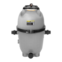
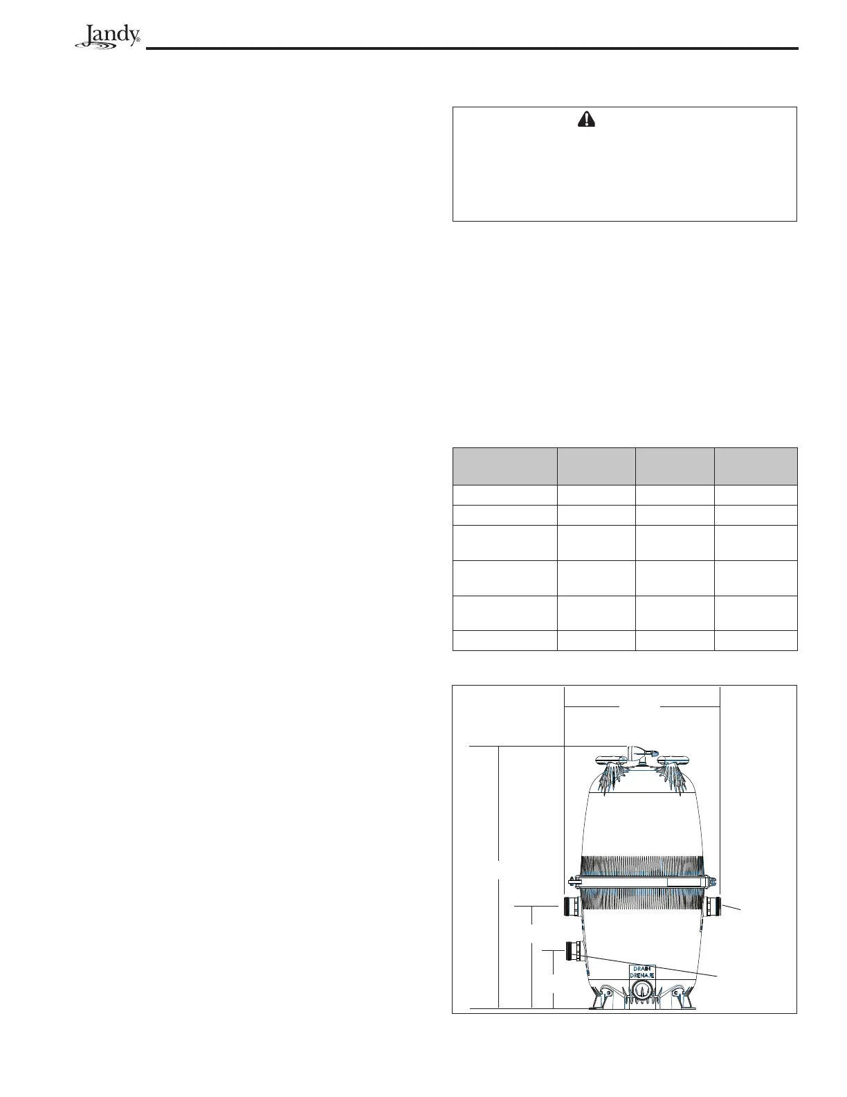
Figure 1 . Dimensions, J andy C L and C V S eries
C artridge Filters
W A RN I N G
Themaximumoperatingpressureforthisfilteris50
p si . N e ve r su b j e ct t h e f i l t e r t o o p e r a t i n g p r e ssu r e
exceeding50psi.Operatingpressuresabove50psi
ca n ca u se t h e l i d t o b e b l o w n o f f , w h i ch ca n r e su l t i n
d e a t h , se r i o u s p e r so n a l i n j u r y , o r p r o p e r t y d a m a g e .
6. When performing hydrostatic pressure tests or
when testing for external leaks of the completed
subjected to does not exceed the maximum
working pressure of any of the components
within the system.
2.4 SpecicationsandDimensions
See Table 1 and Figure 1.
18½ in
10½ in
28 i n
" A "
C L I N LE T
O U T LE T
C V I N LE T
P o r t o n
CV M o d e l
O n l y
P o r t o n
CL M o d e l
O n l y