Page 7
C artridge Pool Filters - C L and C V S eries Filters
on the tank adapter to tighten. Do not
overtighten.
b. Place the larger, thinner o-ring onto the
gauge housing. Thread the housing into the
coupler on the tank adapter.
desired position. Raise and thread the locknut
assembly. Hand tighten the nut only. Using
a wrench to tighten the nut may damage the
nut, gauge or air release assembly.
3.4 Filter Plumbing
properly and operated without air in the water
2. If the system can be subjected to higher pressure
than the maximum rating of any component,
install an ASME approved automatic pressure
relief valve or pressure regulator in the circulation
system. Set the relief valve or pressure regulator to
lowest working pressure of any of the components
in the system.
recommended for plumbing the system.
Sweep Elbow for this purpose. The sweep
elbow also includes a threaded port and plug
pressure testing. See Figure 7.
5.2 To install the sweep elbow use the following
instructions:
W A RN I N G
T o a vo i d a n e l e ct r i ca l sh o ck h a za r d , w h i ch ca n r e su l t
i n se r i o u s i n j u r y o r d e a t h , e n su r e t h a t a l l e l e ct r i ca l
p o w e r t o t h e syst e m i s t u r n e d o f f b e f o r e a p p r o a ch i n g ,
i n sp e ct i n g o r t r o u b l e sh o o t i n g a n y l e a ki n g va l ve s
o r p l u m b i n g t h a t m a y h a ve ca u se d o t h e r e l e ct r i ca l
d e vi ce s i n t h e su r r o u n d i n g a r e a t o g e t w e t .
W A RN I N G
F o l l o w a l l f i l t e r m a n u f a ct u r e r ' s
i n st r u ct i o n s. N E V E R a t t e m p t t o
a sse m b l e , d i sa sse m b l e o r a d j u st t h e
f i l t e r w h e n t h e r e i s p r e ssu r i ze d a i r i n t h e
syst e m . S t a r t i n g t h e p u m p w h i l e t h e r e
i s a n y p r e ssu r i ze d a i r i n t h e syst e m ca n
ca u se t h e f i l t e r l i d t o b e b l o w n o f f , w h i ch
ca n ca u se d e a t h , se r i o u s p e r so n a l
i n j u r y o r p r o p e r t y d a m a g e .
a. Switch off the circuit breaker to the
equipment and open the air relief valve on
procedure).
N O T E Ifthelterisbelowpoollevel,closethesuctionand
returnlinevalvestoisolatetheltrationsystem.
Removethedrainplugfromthelter.Letthewater
drainfromthelter.
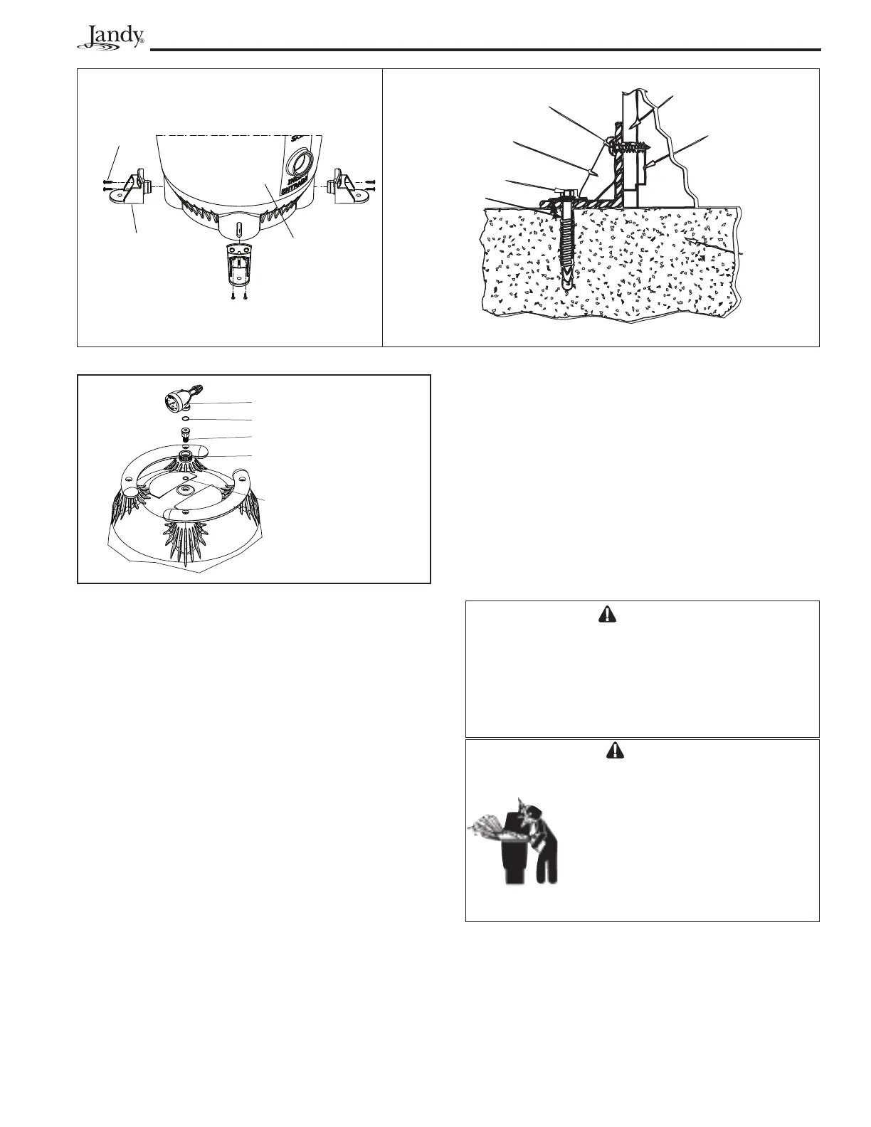
Figure 4 . Pressure G auge/ A ir Release A ssemb ly
H o u si n g
O - R i n g
O - R i n g
T a n k A d a p t e r
T a n k A d a p t e r t o H o u si n g
Co u p l e r
F i l t e r B a s e
D r i l l 5/ 32” H o l e
M o u n t i n g T a b
M o u n t i n g B r a c k e t
# 12x 1” S t a i n l e s s S t e e l P a n
H e a d S c r e w s ( Q t y 2)
D r i l l T w o 3/ 32” H o l e s
T h r o u g h F i l t e r B a s e
1/ 4” x 2- 1/ 4” S . S . T a p c o n
S c r e w a n d S . S . W a s h e r
3- 1/ 2” T h i c k
( M i n . )
Co n c r e t e P a d
A n c h o r
B r a c k e t
( Q t y 4)
# 12x 1” P a n H e a d
S t a i n l e s s S t e e l
S c r e w ( Q t y 8)
T a n k B o t t o m
F i l t e r T a n k A n ch o r B r a cke t I n st a l l a t i o n A n ch o r B r a cke t t o P l a t f o r m I n st a l l a t i o n
Figure 3 . A nc hor B rac k et I nstallation