A WILKINSON STAR LIMITED PRODUCT 01-19 ISSUE 1
ACCESSORIES INFORMATION
Torch switch socket
1. Pin 1, Pin 2 and Pin 3 are for torch current regulaon.
2. Pin 4, Pin 5 and Pin 6 are for digital torch connecons. Pin 4 -, Pin 5 +,
Pin 6 2T/4T.
3. Pin 7 digital/analog torch idencaon pin. Connect pin 9 and 7 for
analog torch use.
4. Pin 8 and Pin 9 are torch switch connecons.
5. The torch switch socket can be connected to a digital torch, analog
torch or foot control switch.
6. Pin 2 is the common terminal of the potenometer. It uses the torch
control wheel 0 as the starng posion. When the current is the
minimum, the resistance of Pin 1 and Pin 2 is 10KΩ and the resistance of
Pin 2 and Pin 3 is 0Ω. When the wheel rotates to the maximum and the
current is the maximum, the resistance of Pin 1 and Pin 2 is 0Ω and the
resistance of Pin 2 and Pin 3 is 10KΩ.
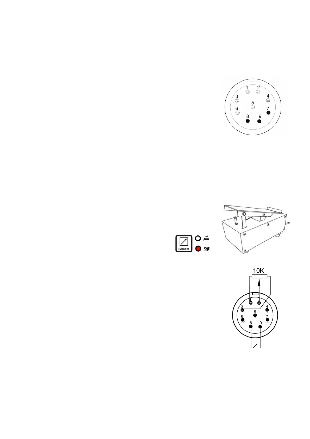
Use of the foot control
1. The pedal remote control consists of a switch and a potenometer, as
shown in the gure.
2. Connect the pedal remote control to Pin 1, Pin 2, Pin 3, Pin 8 and Pin 9
of the torch switch socket on the front panel of the welder.
3. Under no load, press the remote buon to turn on
the indicator. The foot pedal enters the pedal remote
control mode.
4. Adjust the maximum welding current through the panel before
welding.
5. Step on the pedal control to start arc striking. Normally, HF non
contact arc striking is used. When the arc is struck, the welding
current is controlled by the foot pedal control. The maximum
output is the set current.
6. Pin 2 is the common terminal of the potenometer. It uses the
minimum pedal control current as the starng posion. When the
resistance of Pin 1 and Pin 2 is 10 KΩ, the resistance of Pin 2 and Pin 3 is
0Ω. When the pedal is pressed to the end and the current is the
maximum, the resistance of Pin 1 and Pin 2 is 0Ω and the resistance of Pin
2 and Pin 3 is 10KΩ.
TIG torch connecons
1. The wire control welding torch is divided into digital adjustable type and analog adjustable type, as
shown in the gure on the opposite page.
2. Connect the analog adjustable welding torch to Pin 1, Pin 2, Pin 3, Pin 8 and Pin 9 of the torch switch
socket on the front panel of the welder through a special cable. Pin 7 and Pin 9 must be short-circuited.