Page 29
6.2.1 Display of TIG parameters
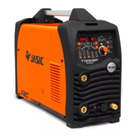
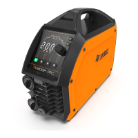
Figure 6-5 TIG200P HD digital panel
1) Pre-flow time indicator. When the indicator is on, it indicates the pre-flow protection
time
2) Initial current indicator. When the indicator is on, it indicates the initial current
3) Up-slope time indicator. When the indicator is on, it indicates the time until the initial
current reaches the peak current
4) Peak current indicator. When the indicator is on, it indicates the welding current
5) Base current indicator. When the indicator is on, it indicates the pulse base current
6) Down-slope time indicator. When the indicator is on, it indicates the time until the
peak current drops to the finish current
7) Finish current indicator. When the indicator is on, it indicates the finish current
8) Post-flow time indicator. When the indicator is on, it indicates the post-flow time
9) Spot welding time indicator. When the indicator is on, it indicates the spot welding
time
10) Pulse frequency indicator. When the indicator is on, it indicates the pulse frequency
11) Duty-cycle indicator. When the indicator is on, it indicates the ratio of peak current
time to pulse period
6.2.2~6.2.3
(Same as 6.1.2-6.1.3)
 Loading...