ASAHI KASEI [AK5358A]
MS0511-E-00 2006/06
- 3 -
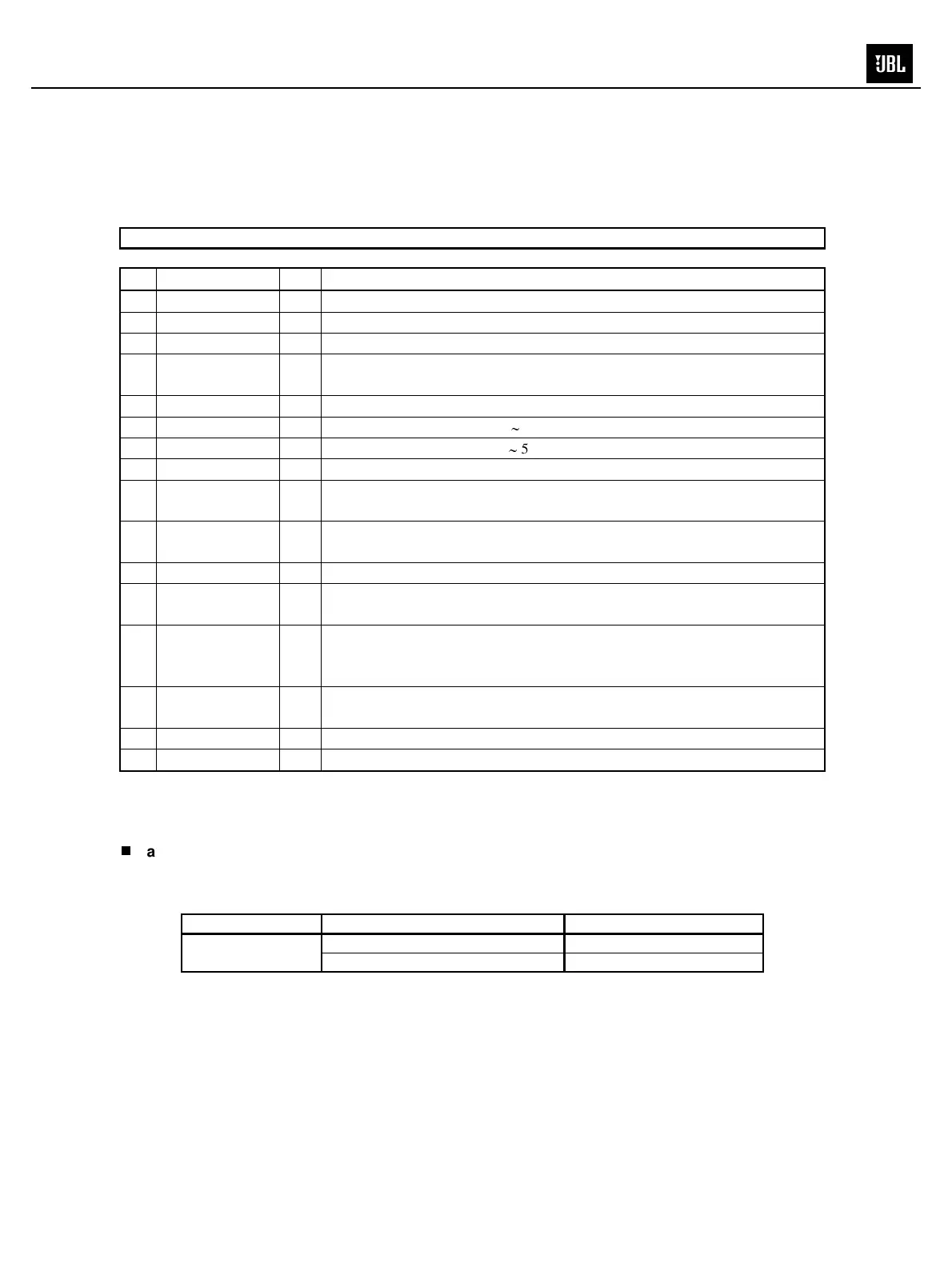
PIN / FUNCTION
No. Pin Name I/O Function
1 AINR I Rch Analog Input Pin
2 AINL I Lch Analog Input Pin
3 CKS1 I Mode Select 1 Pin
4 VCOM O
Common Voltage Output Pin, VA/2
Bias voltage of ADC input.
5 AGND - Analog Ground Pin
6 VA - Analog Power Supply Pin, 4.5
5.5V
7 VD - Digital Power Supply Pin, 2.7
5.5V
8 DGND - Digital Ground Pin
9 SDTO O
Audio Serial Data Output Pin
“L” Output at Power-down mode.
10 LRCK I/O
Output Channel Clock Pin
“L” Output in Master Mode at Power-down mode.
11 MCLK I Master Clock Input Pin
12 SCLK I/O
Audio Serial Data Clock Pin
“L” Output in Master Mode at Power-down mode.
13 PDN I
Power Down Mode & Reset Pin
“H”: Power up, “L”: Power down & Reset
The AK5358A must be reset once upon power-up.
14 DIF I
Audio Interface Format Pin
“H”: 24bit I
2
S Compatible, “L”: 24bit MSB justified
15 CKS2 I Mode Select 2 Pin
16 CKS0 I Mode Select 0 Pin
Note: All input pins except analog input pins (AINR, AINL) should not be left floating.
Handling of Unused Pin
The unused input pins should be processed appropriately as below.
Classification Pin Name Setting
AINL This pin should be open.
Analog
AINR This pin should be open.
 Loading...
