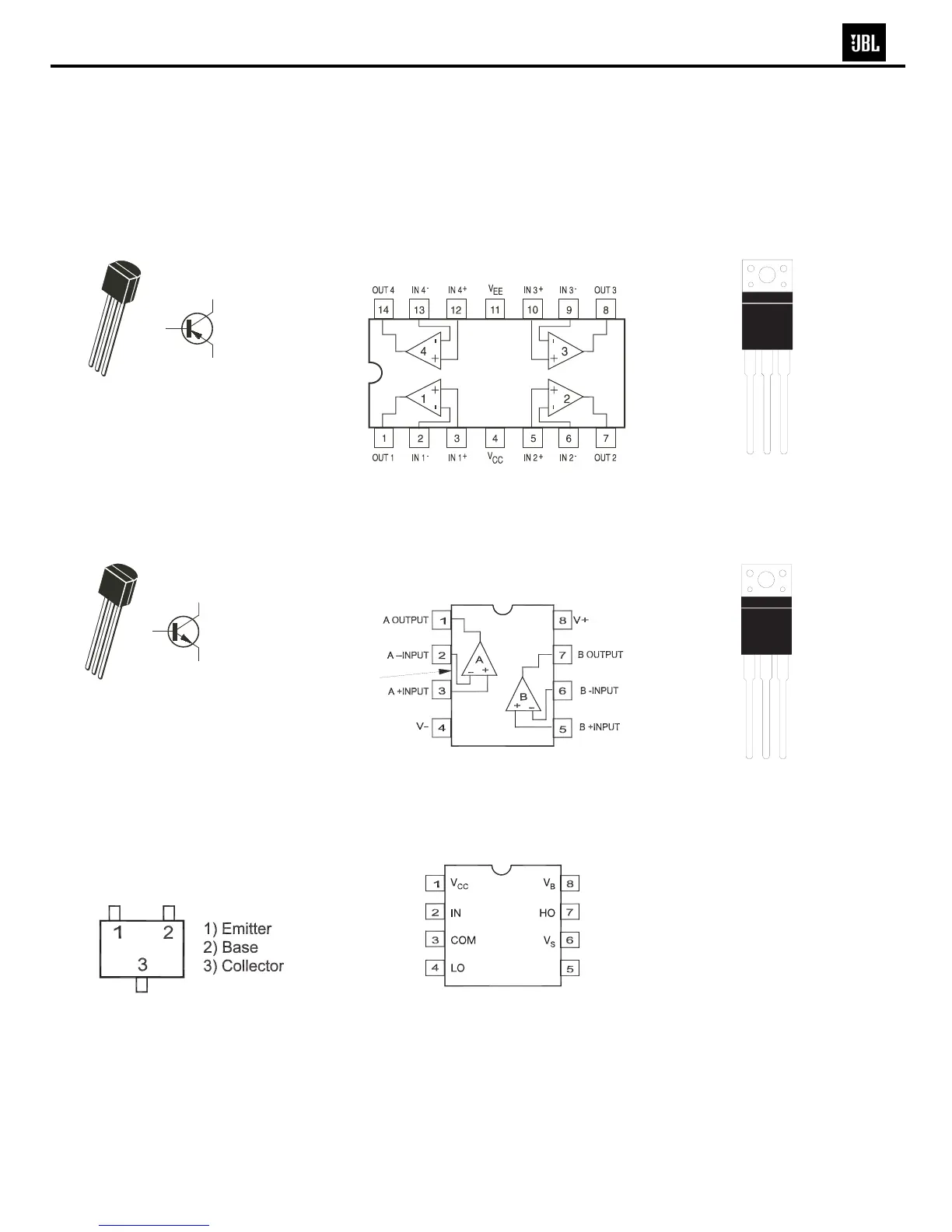
OPAMP, QUAD
TL074CDR
U2, 3
OPAMP, DUAL
TL072CDR SO-8,
NJM4558M-TE3
U5, 6, 4
IR2111 HALF-BRIDGE
DRIVER
U7
2
Base
3 Collector
1 Emitter
1
2
3
2N5401
Q1
2
Base
3 Collector
1 Emitter
1
2
3
MPSW06RLRA,
MPSW56RLRAMPQ,
MPS2222ARLRA,
2N2907A, 2N5551,
Q2, 16, 3, 21, 19, 23, 17
MOSFET IRF640
Q18, 22
TIP31C
Q4
MMBT3904LTI SOT23,
MMBT3906LTI SOT23,
DTC114EK SMT3,
MMBT5401 LTI,
MMBT5551 LTI
Q11, 14, 13, 5, 8, 9, 6, 10,
12, 15, 7, 20, 24, 26, 25
BEVEL
1. G
2. D
3. S
12
3
BC
E
Semiconductor Pinout Diagrams
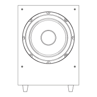
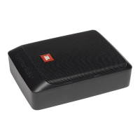
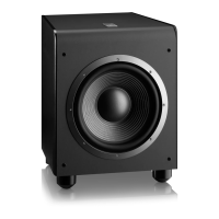
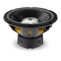
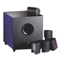
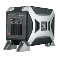
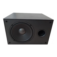
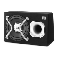
E150P/P10SW subwoofers