2 - 5A
Section E
9803/3280
Section E
2 - 5A
Issue 1
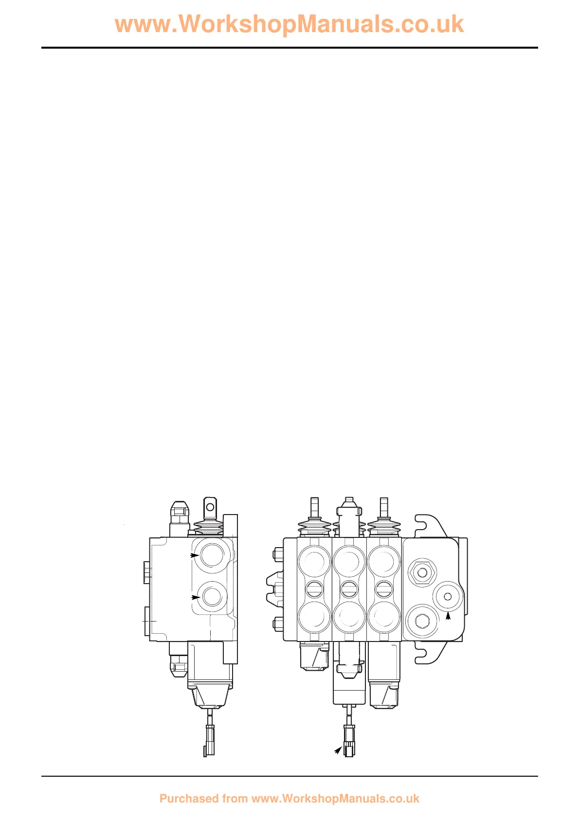
Component Key:
1 Auxiliary (options)
2 Shovel service
3 Arms lift service
4 Auxiliary relief valves
5 Electric detent spool connector
6 Inlet port (secondary pump section P2)
7 Tank port
8 Inlet port (main pump section P1)
9 Service ports
bar kgf/cm
2
lbf/in
2
Auxiliary Relief Valves (A.R.V.)
Shovel Ram Head Side 310 315 4500
Shovel Ram Rod Side 170 175 2500
Note: Instructions for pressure testing and adjustment are described in Service Procedures, Loader Valve - Pressure
Testing.
Relief Valve Pressures
Loader Valve - Precision Control (Servo)
(Machines from January 2003)