33 - 3
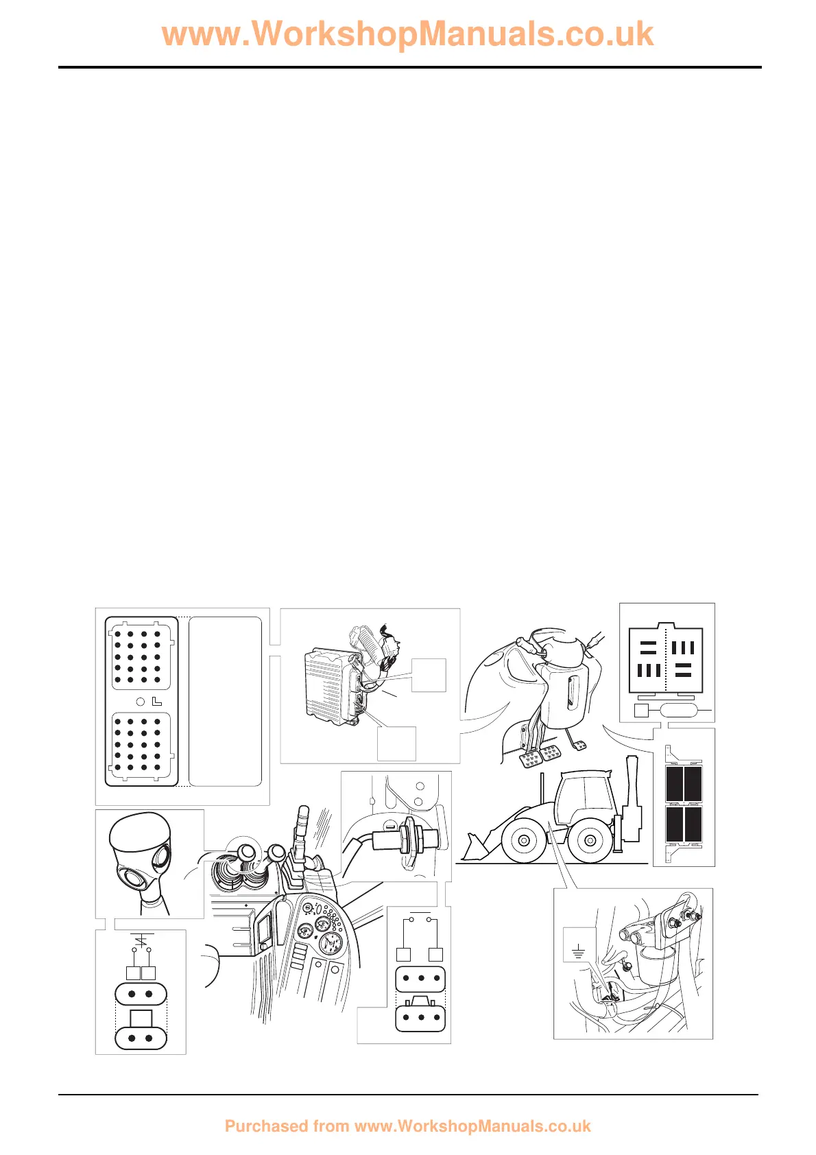
Diagram X
The diagram X (opposite) shows the electrical circuit for the
gearbox control. It is shown with neutral selected and the
park brake ON. ‘Live feed’ wires are coloured red and feed
to earth are green.
Key
A Gearbox solenoids
C50 Reverse alarm
CM Park brake warning light relay
DW Park brake switch
DZ Park brake relay
FL Column switch
FG1 Transmission dump relay
FG2 Reverse alarm relay
GB Harness connector - ECU ‘A’
GC Harness connector - ECU ‘B’
GG Throttle switch
LE Kick down switch
NG Transmission dump switch
Section F Transmission
9803/3280
Section F
33 - 3
Issue 1
Electrical Connections
Powershift Gearbox - 6 Speed
E.C.U. A
Electrical Connections - Quick Reference
The tables show live connector pins and also relevant earth
destinations for given gearbox functions/systems as follows:
E.C.U. feeds and earths
Transmission Dump
Park Brake ON (Transmission Dump)
1, 2, 3, 4(A), 5(A), 6(A) Forward (see following pages)
Neutral (see following pages)
1, 2, 3, 4 Reverse (See following pages)
The information is intended as an aid when checking for
faulty wires or connectors by means of continuity tests using
a multimeter. DO NOT use a multimeter on the ECU
connector pins (connectors A and B). Only test the
associated wiring, uncouple connectors GB and GC and
then use a multimeter at the pins inside these connectors as
applicable. Use the ShiftMaster Diagnostics system to
identify possible faults with the ECU See Powershift
Gearbox - 6 Speed, ShiftMaster Diagnostics - User
Guide.
Note that interconnecting harness connectors are not shown
here. For full details see the relevant expanded harness
schematic in this section.
Note: Identify dump relay FG1 by locating wire 1873 at pin 2
of the corresponding relay base.