1) Twist the moulding pin ¼ of a turn
in either direction to deploy the pin.
2) Pull out and twist ¼ turn in either
direction to lock the pin in the
released position.
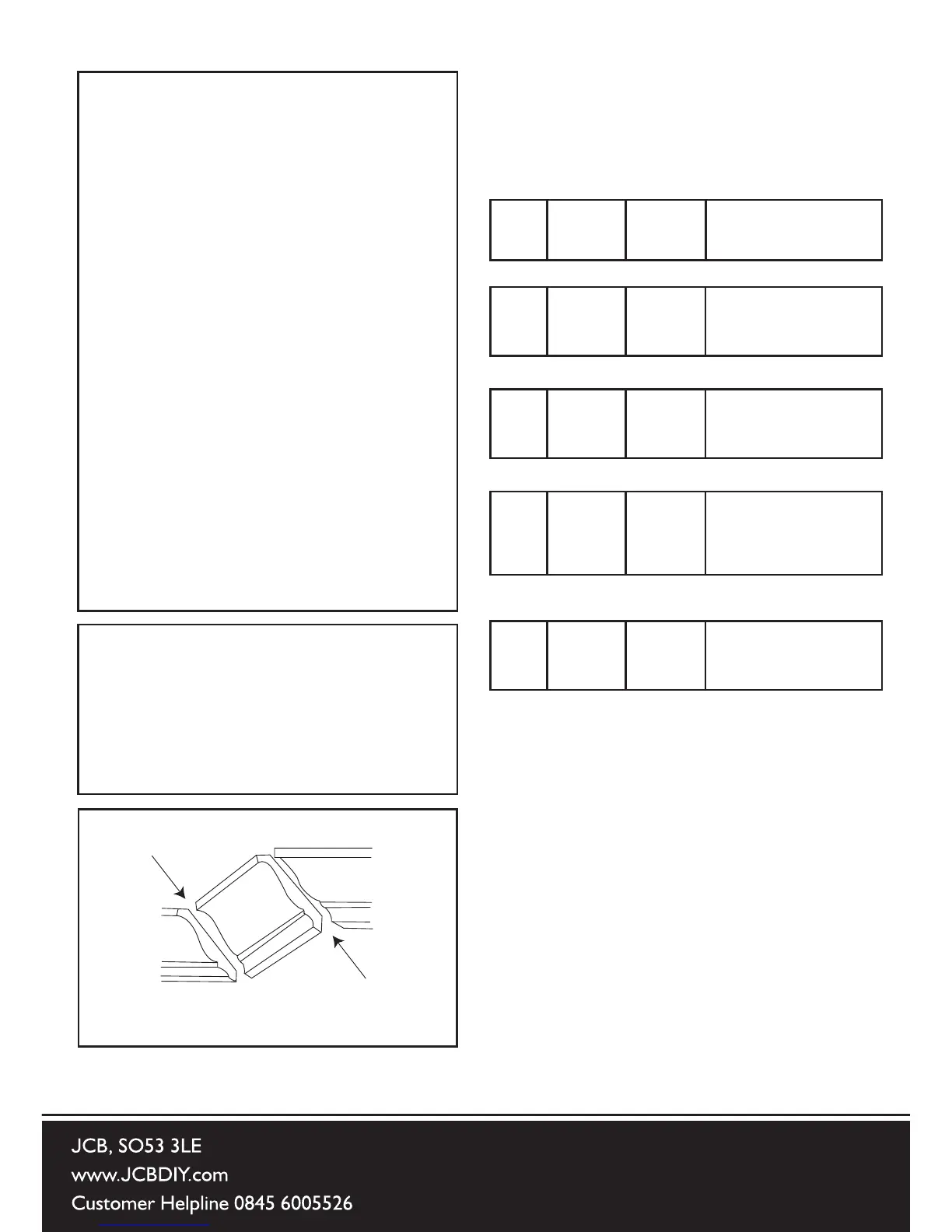
Most crown moulding has a top rear
angle (the section that ts at against
the ceiling) of 52° and a bottom rear
angle (the section that ts at against
the wall) of 38°.
In order to accurately cut crown
moulding for a 90° inside or outside
corner, lay the moulding with its
broad back surface at on the saw
table. When setting the bevel and
mitre angles for compound mitres,
remember that the settings are
interdependent – changing one
changes the other, as well.
Bevel/Mitre Settings for Crown
Moulding
Settings for standard crown moulding
lying at on a compound mitre saw
table.
27
ERBAUER 216MM (8”) SLIDING MITRE SAW
Bevel/Mitre Settings
Settings for standard crown molding lying fl at on
compound mitre saw table
Note: The chart below references a
compound cut for crown molding ONLY
WHEN THE ANGLE BETWEEN THE WALLS
EQUALS 90°.
KEY
BEVEL
SETTING
MITRE
SETTING
TYPE OF CUT
Inside corner-Left side
IL 33.9° 31.6° Right 1) Position top of molding against
fence.
2) Mitre table set at RIGHT 31.6°.
3) LEFT side is fi nished piece.
Inside corner-Right side
IR 33.9° 31.6° Left 1) Position bottom of molding
against fence.
2) Mitre table set at LEFT 31.6°.
3) LEFT side is fi nished piece.
Outside corner-Left side
OL 33.9° 31.6° Left 1) Position bottom of molding
against fence.
2) Mitre table set at LEFT 31.6°.
3) RIGHT side is fi nished piece.
Outside corner-Right side
OR 33.9° 31.6° Right 1) Position top of molding against
fence.
2) Mitre table set at RIGHT 31.6°.
3) RIGHT side is fi nished piece.
IL
IR
OL
OR
Inside Corner
Outside Corner
Compound Cut Crown Moldings
Fig 42
Compound Cut Crown Mouldings
NOTE: The chart below references
a compound cut for crown moulding
ONLY WHEN THE ANGLES
BETWEEN THE WALLS EQUALS 90
0
KEY BEVEL MITRE TYPE OF CUT
SETTING
Inside Corner-Left side
IL 33.9
0
31.6
0
Right
1) Position top of moulding
against fence
2) Mitre table set at Right 31.6
0
3) Left side is nished place
1) Position bottom of moulding
against fence
2) Mitre table set at Right 31.6
0
1) Position bottom of moulding
against fence
2) Mitre table set at Left 31.6
0
3) Right side is nished place
1) Position top of moulding
against fence
2) Mitre table set at Right 31.6
0
3) Right side is nished place
IR 33.9
0
31.6
0
Left
OL 33.9
0
31.6
0
Left
OR 33.9
0
31.6
0
Right
Outside Corner-Left side
SETTING
Inside Corner-Right side
Outside Corner-Right side