4 - 10
Travel Motor Relief Pressure
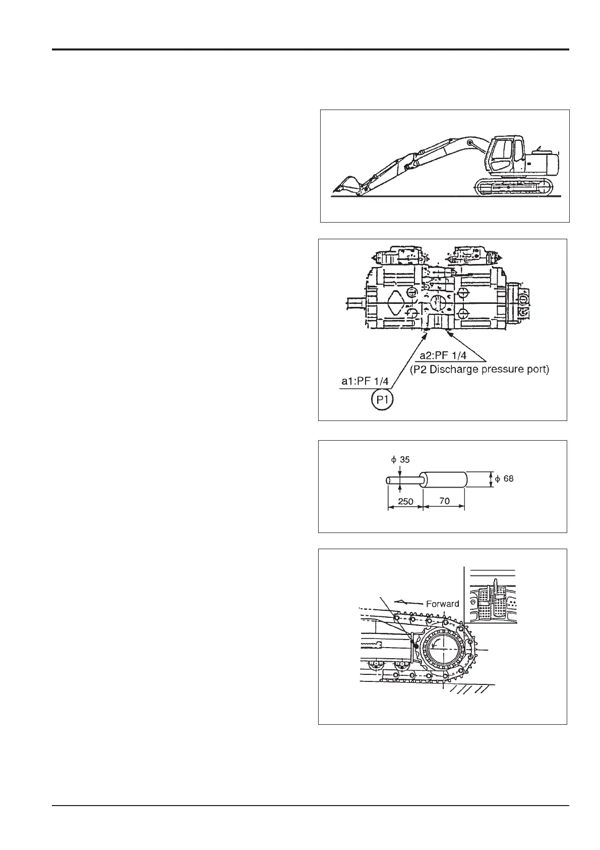
1. Prepare the Machine
a. Put the operator lever into neutral, lower the gate
lock lever, start the engine and place the machine on
level ground, lower and open the dipper and set the
bucket on the ground.
b. Stop the engine and release hydraulic pressure.
(See Releasing Tank Pressure).
c. Connect a 0-500 bar (0-7000 lb/in
2
) pressure gauge
and adaptor to port P1 (left travel), P2 (Right travel).
Note: Because the travel motor relief pressure is higher than
the relief pressure, raise the main relief pressure to more
than 350 bar (5120 lb/in
2
).
2. Refer to the section "Temporary Setting of main relief
pressure" and complete step 2.
3. Insert lock pin A into the drive sprocket, on the
appropriate side being measured.
4. Pressure Adjustment
a. Start the engine and lower the gate lock lever, run
the engine at maximum no-load speed in the S
mode.
b. Slowly engage the travel motor left or right whichever
is locked up.
c. Check the gauge for the set pressure of 402 bar ± 20
bar (5830 ± 284 lb/in
2
). If it is outside the limits, adjust
the port relief valve A by loosening the lock nut B and
always coming up to the correct set pressure by first
unscrewing, and then screwing in adjusting screw C.
d. Repeat the procedure from step 3 for the other side.
Section E
Hydraulics
9803/6400
Section E
4 - 10
Issue 1
Pressure Testing
A

 Loading...


