94 - 6
Section E
Hydraulics
9803/6400
Section E
94 - 6
Issue 2*
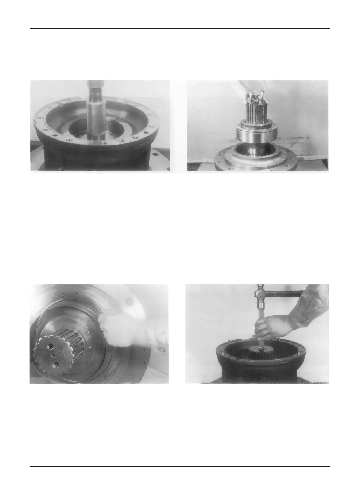
Slew Motor
*
5 Degrease the periphery of oil seal 61 and its mounting
face in gear case 58 and apply JCB High Strength
Retainer to these surfaces. Press the oil seal into the
gear case using a jig. Grease the oil seal after it has
been pressed into place.
Note: Refer to seal press-fitting jig in the Service Tools
section.
6 Use the seal protector to prevent the splines of pinion
shaft 53 from scratching the lip of the oil seal.
(Refer to the Service Tools section for the seal
protector.)
a Turn gear case 58 so that the output shaft is
upwards and mount the pinion shaft assembly 53
onto the gear case using an M16 eye bolt screwed
into the tapped hole in the output end of the pinion
shaft.
b To prevent the seal protector hitting the work bench,
place 150 mm (6 in) blocks under gear case 58.
Reduction Gear
Assembly (cont’d)
7 Mount the snap ring 55.
To make it easy to remove the snap ring again, position
the gap in the snap ring approx. 30 mm (1.2 in) away
from the notch in the gear case.
8 Turn the output shaft of the gear case downwards. Heat
the inner ring of the roller bearing 62 to 50°C over the
ambient temperature and mount it on the shaft.

 Loading...


