6 - 4
Replacement (continued)
4. a. Install the covers over the motor.
b. Check the amount of oil in the gearbox.
c. Bleed air from the motor (see Motor Bleeding).
d. If the traction motor has been dismantled and
serviced, carry out the functional tests detailed
under Testing later in this section.
e. Install the drive sprocket (see Drive Sprocket,
Replacement, Section J).
f. Remove the wooden blocks.
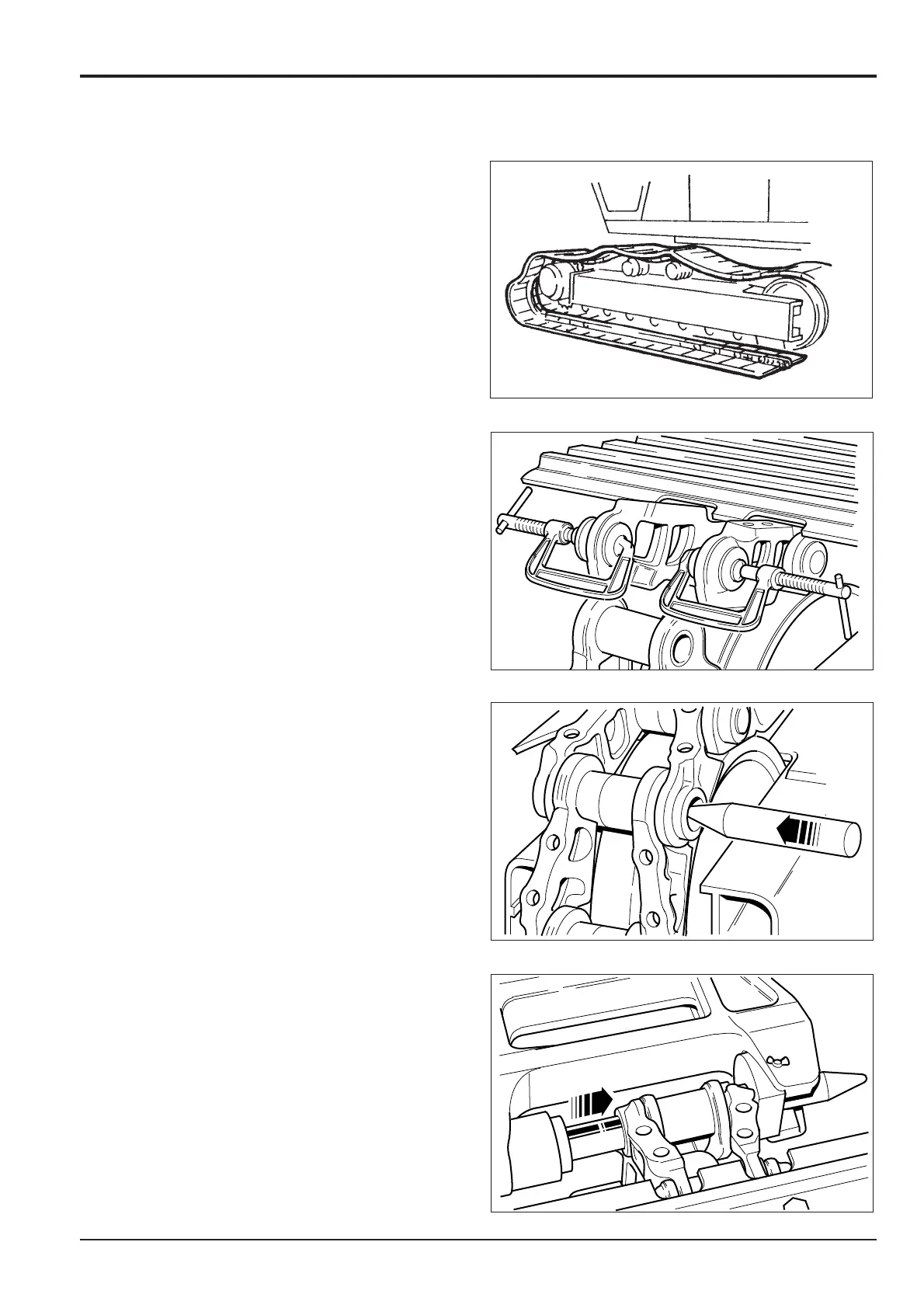
g. Position the lower frame on the track.
h. Move the track link by reversing step 1 of Removal.
i. Clean the seal ring housings in the chain link. Insert
the seal rings and clamp into position.
j. Using a plastic hammer, tap the upper link down to
align holes.
Note: As the links overlap, the seal rings will be held in
position. Remove ‘G’ clamps.
k. Insert the pointed guide pin from the inner face and
tap through its full length.
l. Position a suitable hydraulic press so that its ram
aligns with the guide pin.
m. Insert the master pin into its locating hole.
n. Slowly operate the hydraulic ram and press the
master pin into position.
o. Re-locate the track shoes and tighten the bolts (see
Checking Shoe Plate, Routine Maintenance,
Section 3).
Section F
Transmission
9803/6400
Section F
6 - 4
Issue 2*
Motor/Gearbox

 Loading...


