7 - 1
Dismantling
Note: The numbers in the following section refer to the
illustrations on pages F/7-15 and F/7-16.
Before starting the dismantling, drain the oil, clean all the
surfaces with a suitable solvent and dry with compressed air.
Discard all 'O'-rings and seals which are disturbed during
dismantling.
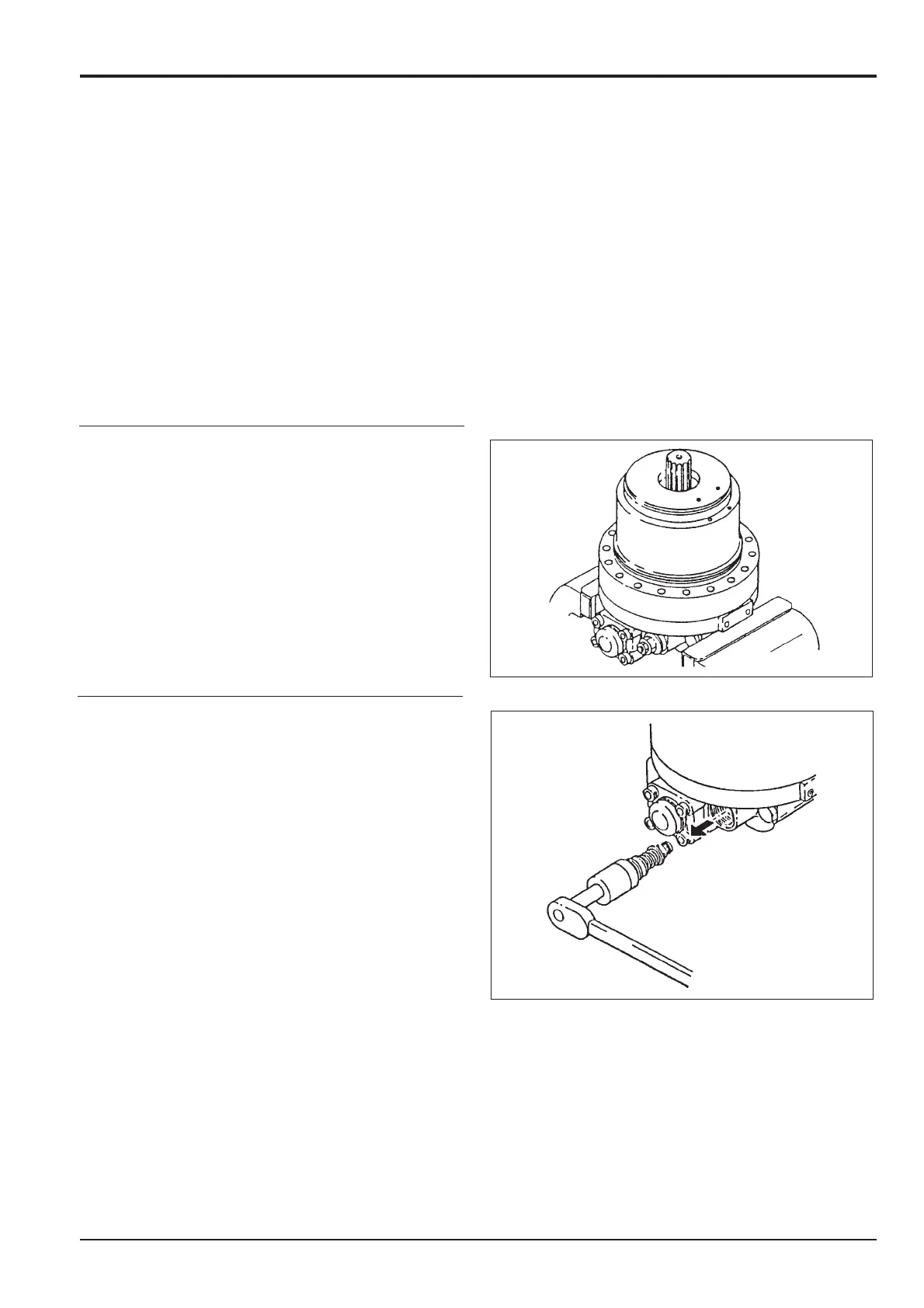
1. With the motor/gearbox assembly removed from the
machine as described in the previous section.
Unscrew the three socket head screw and separate the
hydraulic motor from the gearbox.
2. Remove the O ring from its groove in the motor.
3. Fix the motor into a suitable vice or jig with the shaft
facing upwards.
4. Base plate disassembly
a. Relief valve disassembly.
Loosen the plug (2-7-6) and remove the relief valve
sub-assembly (2-7).
b. The (2-7-6) plug and (2-7-1) relief housing are
press fitted but the (2-6-2) poppet is not.
Remove the (2-7-3) poppet seat from the (2-1)
housing using the poppet seat removal jig.
Note: When removing the (2-7) relief valve sub-assembly, the
relief set pressure will be lost if the (2-7-16) nut and (2-7-15)
set screw are loosened, so take care not to loosen them. Do
not disassemble the relief valve unless absolutely necessary.
Section F
Transmission
9803/6400
Section F
7 - 1
Issue 2*
Motor
*
*
*

 Loading...


