8 - 20
Section F Transmission
9803/6020
Section F
8 - 20
Issue 1
Track Gearbox
Inspection (cont’d)
Part(s) Inspection Standard Permissible Measuring Corrective Action
Measurement Value Tolerance/ Tool
Area Condition
k. Timing plate Wear for cylinder Surface Wear 0.005 mm Contour/ Lap the slide surface
109 block 104 roughness (0.0002 in) roughness to correct any slide
0.4S tester damage. (Correctable wear
0.020 mm)
m. Spool 123/ Clearance between Clearance Clearance Indicator
rear flange outer diameter of 0.012 - 0.038 mm micrometer
101 spool 123 and spool 0.018 mm (0.0015 in) Cylinder gauge
hole of rear flange (0.0005 -
101 0.0007 in)
n. Piston Backlash of ball joint Backlash Backlash 0.2 mm Lever type dial
assembly between piston 161 0.1 mm (0.008 in) gauge
161/162 and shoe 162 (0.004 in)
p. Brake Outer surface Surface No scratches, Visual check
friction roughness uneven wear or
plate 115 12S thermal seizure
Plate thickness 2.8 mm Min. 2.5 mm Slide calipers
(0.11 in) (0.1 in) or cross and visual
groove must check
remain.
2 Measurement Procedures
Component measurements should be carried out in a
clean area, i.e. free from dust and contaminants, where
the temperature is 18 °C - 20 °C (64.4 °F - 71.6 °F).
After thorough cleaning arrange the components on a
working surface of JIS Class 2 or better.
Take measurements carefully and at least twice to verify
accuracy.
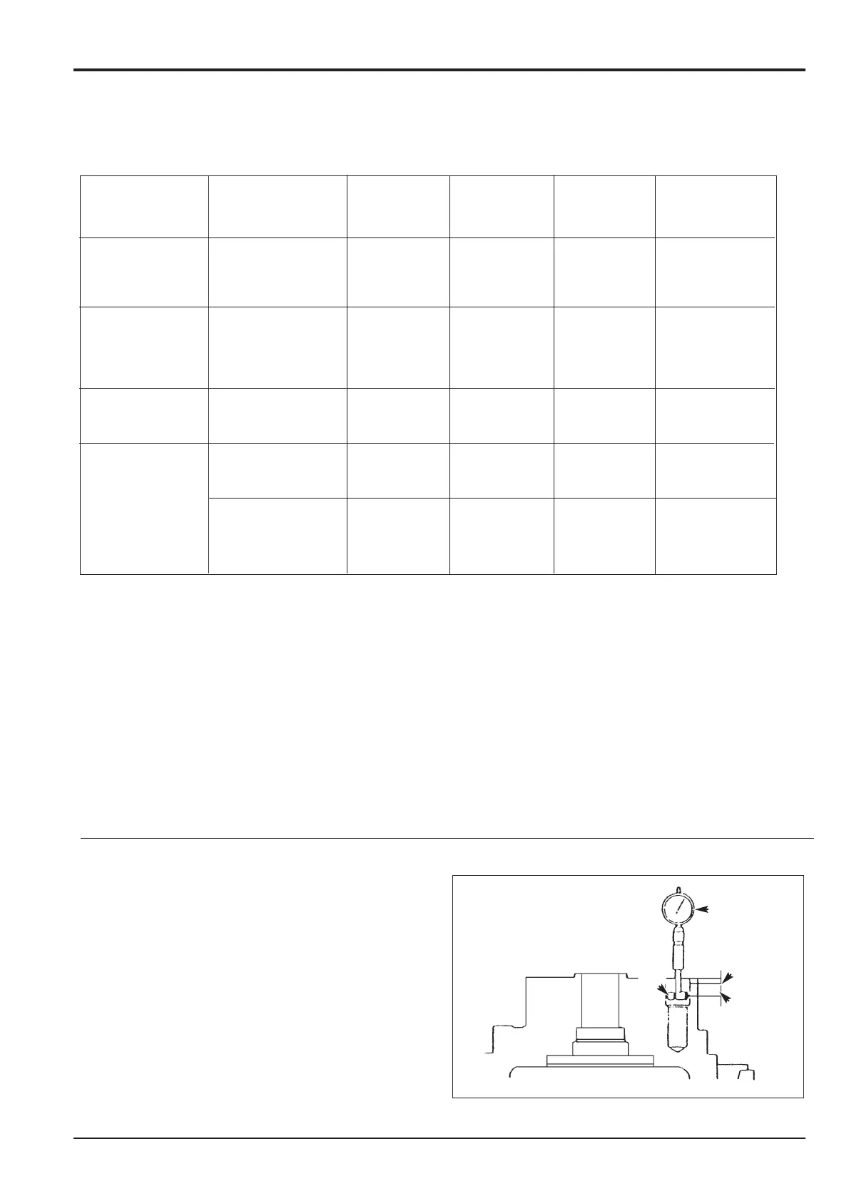
a Measurement of spindle 2 reamer hole bore
diameters - use a 1 mm full scale dial gauge C and
a cylinder gauge D of measuring range 18 - 35
mm. Set up the dial gauge - insert the cylinder
gauge into a 19 mm standard ring gauge and zero
the dial scale.
Transfer the cylinder gauge to one of the reamer
holes and measure the diameter 3 mm down (point
A) and then 10 mm down (point B). Rotate the
cylinder gauge two or three times at each point and
make a note of the minimum reading. For tolerance
see Wear Limits Table, item 1 (b).
Repeat for the other two reamer holes.
299610
10
3
CC
AA
BB
DD
 Loading...