Part No. 960-000187R_Rev. A © 2016 JCM American Corporation
November, 2016 JCM® Training Overview DBV-500 Banknote Validator
JCM TOOL SUITE STANDARD EDITION
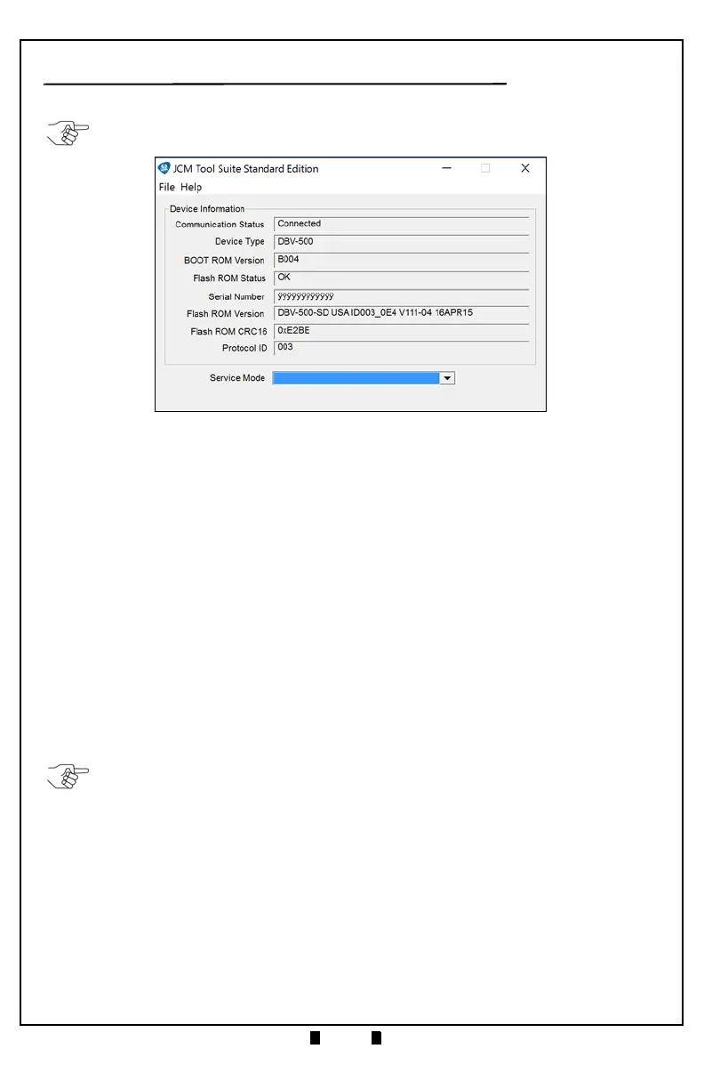
Figure 4 illustrates the JCM Tool Suite Standard Edition’s Main Screen.
The JCM Tool Suite Standard Edition supports the following operational
modes and User-selectable Functions, under the “Service Mode” drop-down
Menu:
The available Service Mode Functions include:
• Normal Mode or Operational Mode
(All DIP Switch Block #1 Switches = OFF):
– Download
– Statistics
– Event Log View
• Test Mode (DIP Switch Block #1 Switch #8 = ON):
– Download
– Statistics
– Sensor Adjustment
– Performance Test
– Event Log View
Use a Standard USB Type-A to Mini-B Cable between the PC and DBV-500.
1. Remove the Cash Box.
2. Connect the Mini-B cable to the USB Port by the DIP Switches.
3. Connect the Type-A connector to the USB Port on the PC.
4. Apply power to the DBV-500 Unit.
5. Open the JCM Tool Suite Application. When connected, the Device Information
Fields will be filled in, as shown in Figure 4.
NOTE:
For DBV-500, JCM Tool Suite Version 1.29 or higher is required.
Figure 4 JCM Tool Suite Main Screen
NOTE:
All Diagnostics Tests can also be performed by setting various DIP Switch
settings. For more information on setting the DIP Switches for testing, refer to Section 6
in the DBV
®
Series DBV-500 Operation and Maintenance Manual (
P/N 960-100933R
{EDP #233449}
).