Part No. 960-000187R_Rev. A © 2016 JCM American Corporation
DBV-500 Banknote Validator JCM® Training Overview November, 2016
CALIBRATION
Calibration of the DBV-500 Unit needs to be performed when any of the
following conditions occur:
• When removing and replacing the CPU Circuit Board
• When removing or replacing any Sensors or Sensor Boards
• After cleaning the DBV-500 Unit
• If the Banknote Acceptance rate has decreased.
V
ALIDATION
S
ENSOR
C
ALIBRATION
To perform the DBV-500 Validation Sensor Calibration procedure:
1. Disconnect power from the DBV-500 Unit.
2. Set DIP Switch Block #1, Switch # 8 to ON.
3. Restore power to the DBV-500 Unit.
4. Connect the USB Type-A to Mini-B cable between your PC’s USB port and the
USB port located on the DBV-500 Unit.
5. Launch the
“JCM Tool Suite Standard Edition” software application.
6. Click the
Service Mode drop-down menu (Figure 5), then click Sensor Adjust-
ment.
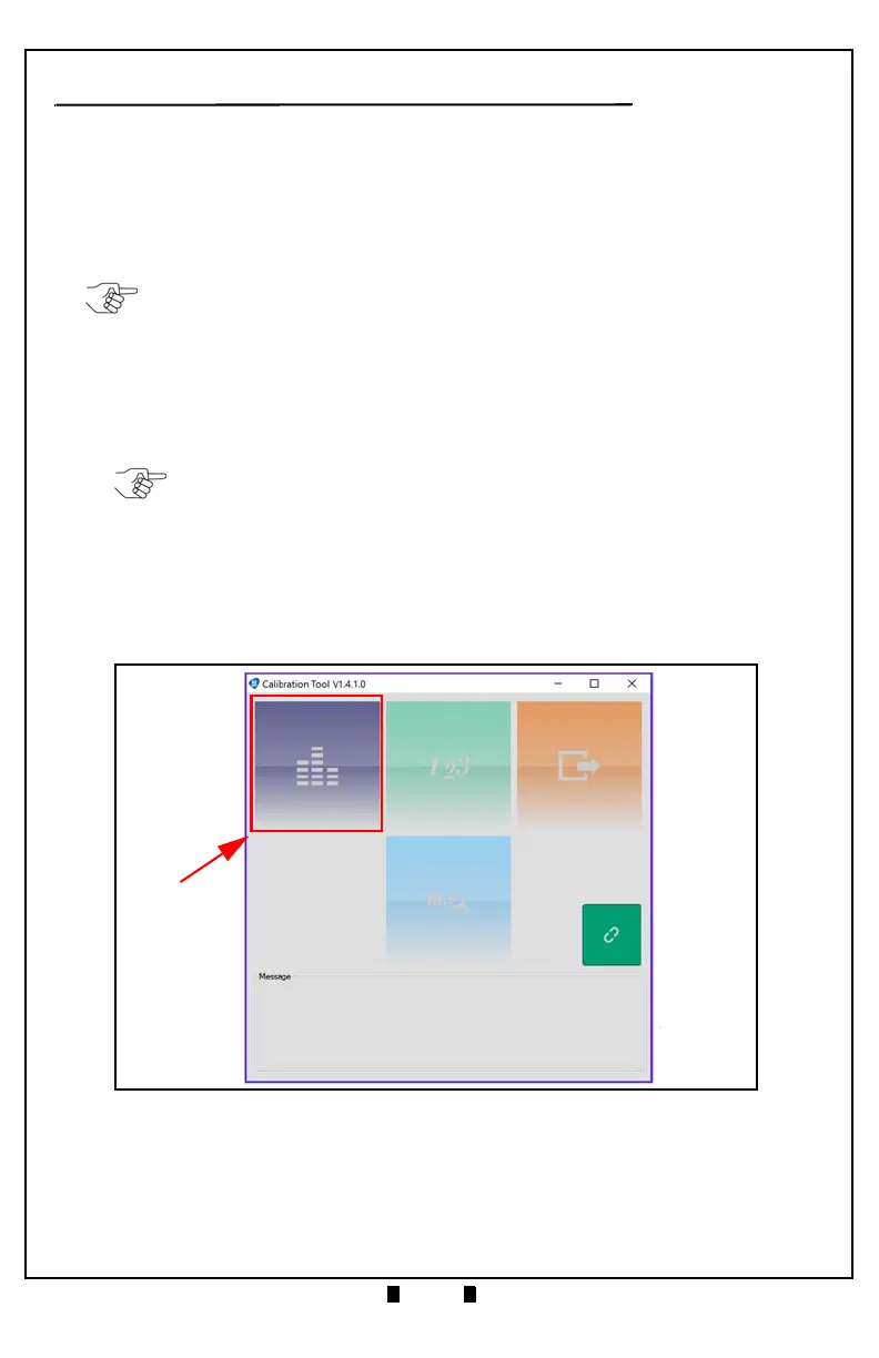
7. Confirm that the DBV-500 Calibration Tool is running, as shown in Figure 8.
8. Click the Sensor Calibration function screen button (Figure 8 a).
The Sensor Calibration screen appears momentarily (refer to Figure 9).
NOTE: KS-091 Reference Paper is specified for use when calibrating the DBV-500.
NOTE: The DBV-500 Unit’s Front Bezel LED will flash Green.
Figure 8 DBV-500 Calibration Tool