EasyManuals Logo

JCM DBV Series Manual

JCM DBV Series
24 pages
To Next Page IconTo Next Page
To Previous Page IconTo Previous Page
Page #4 background imageLoading...
Page #4 background image
Part No. 960-000187R_Rev. A © 2016 JCM American Corporation
4
DBV-500 Banknote Validator JCM® Training Overview November, 2016
COMPONENT LOCATIONS
C
OMPONENT
N
AMES
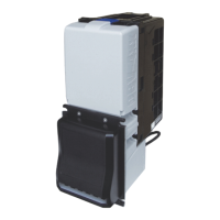
Figure 2 illustrates the DBV-500 Component Names and Locations.
n
m
l
k
Figure 2 DBV-500 Component Names
a) Bezel
b) Full-Color Indicator
c) Transport Unit
d) Cash Box
e) Cash Box Latches
f) Unit Guide Open/Close Latches
g) USB Connector (for Maintenance)
h) Power/Interface Connector
i) DIP Switch Block #1
j) DIP Switch Block #2
k) Cash Box Handle
l) Frame Lock
m) Plastic Latch
n) Metal Lock

Other manuals for JCM DBV Series

Questions and Answers:

Question and Answer IconNeed help?

Do you have a question about the JCM DBV Series and is the answer not in the manual?

JCM DBV Series Specifications

General IconGeneral
BrandJCM
ModelDBV Series
CategoryBank Note Validator
LanguageEnglish

Related product manuals