Part No. 960-000187R_Rev. A © 2016 JCM American Corporation
November, 2016 JCM® Training Overview DBV-500 Banknote Validator
12.When the “Write EEPROM Succeeded” prompt appears, click the “OK” screen
button to close the screen. Then click the
Close box (Figure 10 b) to close the
Sensor Calibration Screen and complete the Calibration process.
W
HITE
L
EVEL
T
EST
To perform the DBV-500 White Level Test procedure:
1. Disconnect power from the DBV-500 Unit.
2. Set DIP Switch Block #1, Switch # 8 to ON.
3. Restore power to the DBV-500 Unit.
4. Connect the USB Type-A to Mini-B cable between your PC’s USB port and the
USB port located on the DBV-500 Unit.
5. Launch the “JCM Tool Suite Standard Edition” software application.
6. Click the
Service Mode drop-down menu, then click Sensor Adjustment.
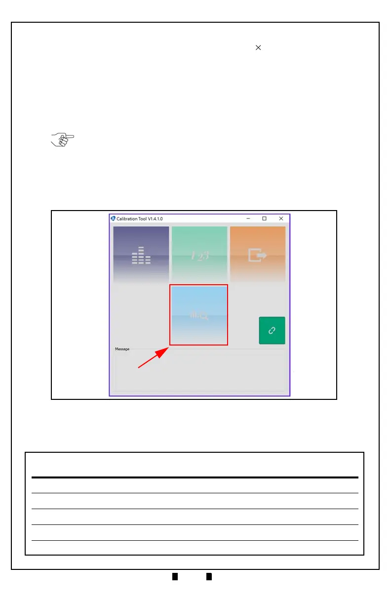
7. Confirm that the DBV-500 Calibration Tool is running, as shown in Figure 11.
8. Click the White Level Test function screen button (Figure 11 a).
The White Level Test screen appears momentarily (refer to Figure 12).
NOTE: The DBV-500 Unit’s Front Bezel LED will flash Green.
Figure 11 DBV-500 Calibration Tool
 Loading...


