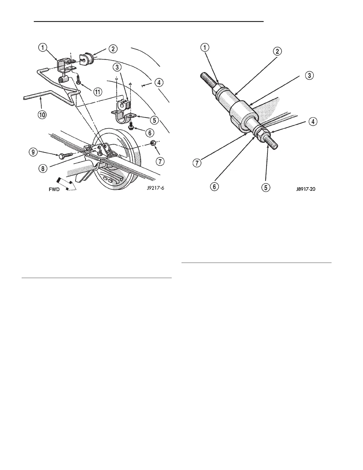
(1) Assemble tools shown (Fig. 3). Tighten nut at
the socket wrench end of the threaded rod until the
bushing is forced out.
(2) Assemble and align the bushing installation
tools.
(3) Align the bushing with the spring eye or
shackle eye and tighten the nut at the socket wrench
end of the threaded rod. Tighten until the bushing is
forced into the spring eye.
NOTE: The bushing must be centered in the spring
eye. The ends of the bushing must be flush or
slightly recessed within the end surfaces of the
spring eye.
(4) For front bushings bend tabs up after installa-
tion.
SPECIFICATIONS
TORQUE CHART
DESCRIPTION TORQUE
Shock Absorber
Upper Bolt ............... 23N·m(17ft.lbs.)
Lower Nut ............... 62N·m(46ft.lbs.)
Stabilizer Bar
Clamp Bolt ............... 54N·m(40ft.lbs.)
Link Upper Bolt ........... 12N·m(9ft.lbs.)
Link Lower Nut ........... 74N·m(55ft.lbs.)
Spring
U-Bolt Nut ............... 70N·m(52ft.lbs.)
Front Pivot Bolt ......... 156N·m(115ft.lbs.)
Upper Shackle Bolt ...... 156N·m(115ft.lbs.)
Lower Shackle Bolt ....... 108N·m(80ft.lbs.)
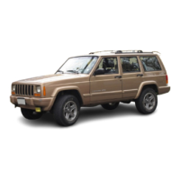
Fig. 2 Stabilizer Bar
1 – LINK
2 – BUSHING
3 – GROMMET
4 – FRAME RAIL
5 – CLAMP
6 – SCREW
7 – NUT
8 – SPRING BRACKET
9 – BOLT
10 – SWAY BAR
11 – SCREW
Fig. 3 Spring Eye Bushing Removal
1 – NUT
2 – PIPE
(RECEIVER)
3 – SPRING EYE
4 – NUT
5 – THREADED ROD
6 – FLAT WASHER
7 – SOCKET WRENCH
(DRIVER)
XJ SUSPENSION 2 - 19
REMOVAL AND INSTALLATION (Continued)