PROPELLER SHAFT JOINT ANGLE
DESCRIPTION
When two shafts come together at a common joint,
the bend that is formed is called the operating angle.
The larger the angle, the larger the amount of angu-
lar acceleration and deceleration of the joint. This
speeding up and slowing down of the joint must be
cancelled to produce a smooth power flow.
OPERATION
This cancellation is done through the phasing of a
propeller shaft and ensuring that the proper propel-
ler shaft joint working angles are maintained.
A propeller shaft is properly phased when the yoke
ends are in the same plane, or in line. A twisted
shaft will make the yokes out of phase and cause a
noticeable vibration.
When taking propeller shaft joint angle measure-
ments, or checking the phasing, of two piece shafts,
consider each shaft separately.
Ideally the driveline system should have;
• Angles that are equal or opposite within 1
degree of each other.
• Have a 3 degree maximum operating angle.
• Have at least a 1/2 degree continuous operating
(propeller shaft) angle.
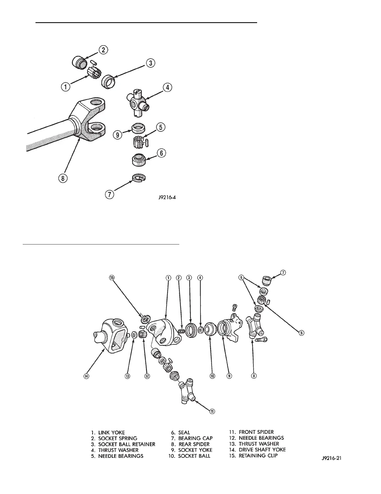
Fig. 4 Double Cardan (CV) Universal Joint
Fig. 3 Single Cardan Universal Joint
1 – NEEDLE BEARING 6 – BEARING CAP
2 – BEARING CAP 7 – RETAINING CLIP
3 – SEAL 8 – YOKE
4 – SPIDER 9 – SEAL
5 – NEEDLE BEARING
XJ PROPELLER SHAFTS 3 - 3
DESCRIPTION AND OPERATION (Continued)











 To Next Page