• fuel tubes/lines/hoses
• quick-connect fittings
• fuel injector rail
• fuel injectors
• fuel tank
• fuel tank filler/vent tube assembly
• fuel tank filler tube cap
• accelerator pedal
• throttle cable
OPERATION
Fuel is returned through the fuel pump module
and back into the fuel tank through the fuel filter/
fuel pressure regulator. A separate fuel return line
from the engine to the tank is not used.
The fuel tank assembly consists of: the fuel tank,
fuel pump module assembly, fuel pump module lock-
nut/gasket, and rollover valve (refer to Group 25,
Emission Control System for rollover valve informa-
tion).
A fuel filler/vent tube assembly using a pressure/
vacuum, 1/4 turn fuel filler cap is used. The fuel
filler tube contains a flap door located below the fuel
fill cap.
Also to be considered part of the fuel system is the
evaporation control system. This is designed to
reduce the emission of fuel vapors into the atmo-
sphere. The description and function of the Evapora-
tive Control System is found in Group 25, Emission
Control Systems.
Both fuel filters (at bottom of fuel pump module
and within fuel pressure regulator) are designed for
extended service. They do not require normal sched-
uled maintenance. Filters should only be replaced if
a diagnostic procedure indicates to do so.
FUEL PUMP MODULE
DESCRIPTION
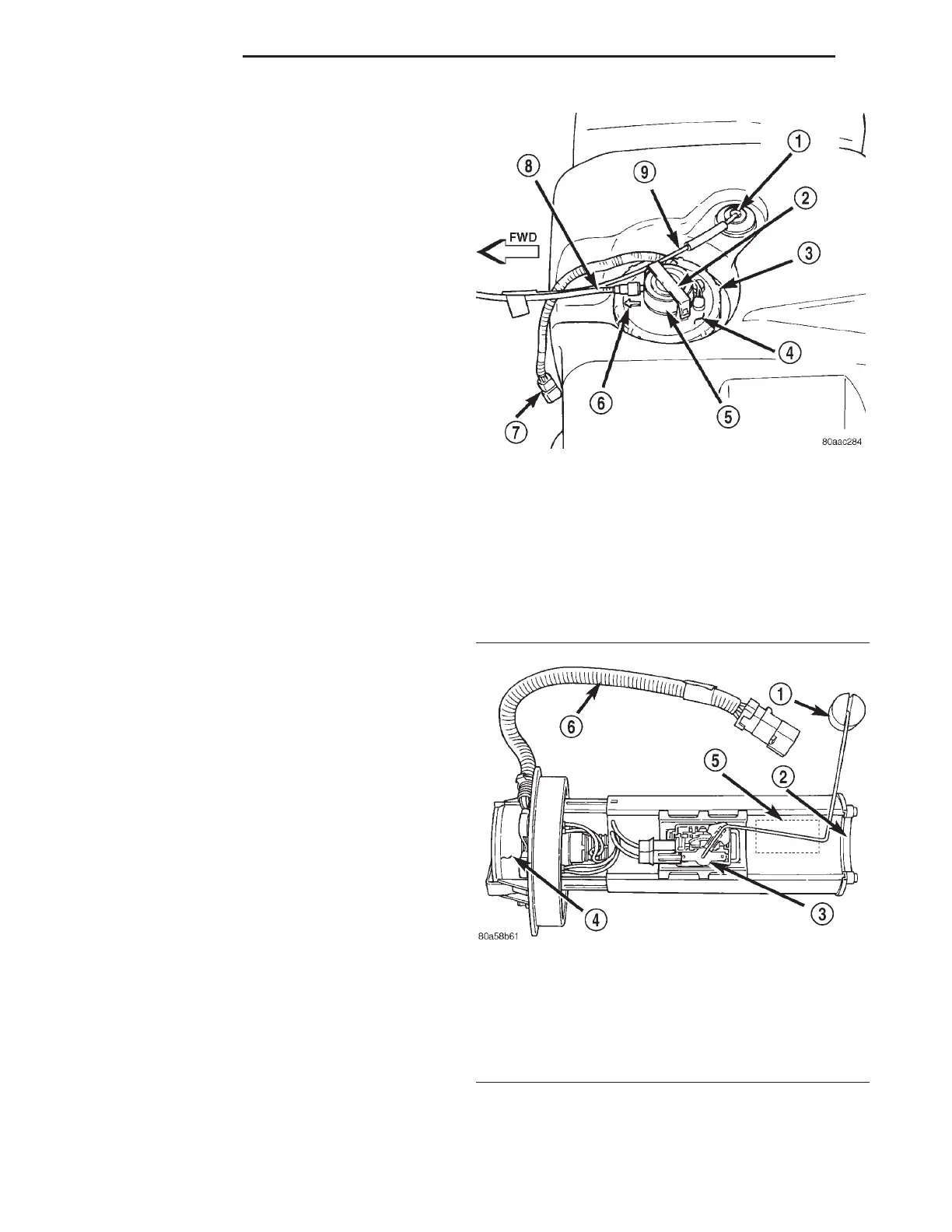
The fuel pump module is installed in the top of the
fuel tank (Fig. 1) or (Fig. 2). The fuel pump module
contains the following components:
• A combination fuel filter/fuel pressure regulator
• A separate fuel pick-up filter (strainer)
• An electric fuel pump
• A threaded locknut to retain module to tank
• A gasket between tank flange and module
• Fuel gauge sending unit (fuel level sensor)
• Fuel supply tube (line) connection
The fuel gauge sending unit, pick-up filter and fuel
filter/fuel pressure regulator may be serviced sepa-
rately. If the electrical fuel pump requires service,
the entire fuel pump module must be replaced.
OPERATION
Refer to Fuel Pump, Fuel Filter/Fuel Pressure Reg-
ulator and Fuel Gauge Sending Unit.
Fig. 1 Fuel Tank/Fuel Pump Module (Top View)
1 – ROLLOVER VALVE
2 – RETAINER CLAMP
3 – LOCKNUT
4 – FUEL PUMP MODULE
5 – FUEL FILTER/FUEL PRESSURE REGULATOR
6 – ALIGNMENT ARROW
7 – PIGTAIL HARNESS
8 – FUEL SUPPLY TUBE
9 – EVAP CANISTER VENT LINE
Fig. 2 Fuel Pump Module Components
1 – FUEL GAUGE FLOAT
2 – PICK-UP FILTER
3 – FUEL GAUGE SENDING UNIT
4 – FUEL FILTER/FUEL PRESSURE REGULATOR
5 – ELECTRIC FUEL PUMP
6 – PIGTAIL WIRING HARNESS
14 - 2 FUEL SYSTEM XJ
DESCRIPTION AND OPERATION (Continued)