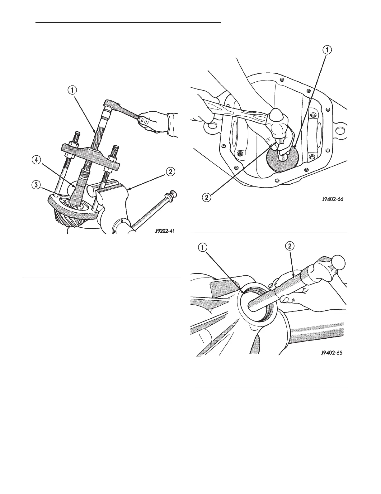
(10) Remove the rear pinion bearing from the pin-
ion with Puller/Press C–293-PA and Adapters
C–293–39 (Fig. 56).
Place 4 adapter blocks so they do not damage
the bearing cage.
(11) Remove the depth shim/oil slinger from the
pinion shaft. Record the thickness of the depth shim/
oil slinger.
INSTALLATION
NOTE: A pinion depth shim/oil slinger is placed
between the rear pinion bearing cone and the pin-
ion head to achieve proper ring gear and pinion
mesh. If the factory installed ring gear and pinion
are reused, the pinion depth shim/oil slinger should
not require replacement. Refer to Pinion Gear Depth
to select the proper thickness shim/oil slinger
before installing pinion.
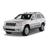
(1) Apply Mopart Door Ease, or equivalent, stick
lubricant to outside surface of rear pinion bearing
cup. Install the bearing cup with Installer D-146 and
Driver Handle C–4171 (Fig. 57). Verify cup is cor-
rectly seated.
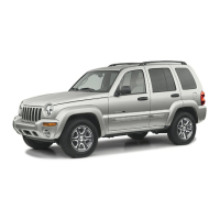
(2) Apply Mopart Door Ease, or equivalent, stick
lubricant to outside surface of front pinion bearing
cup. Install the bearing cup with Installer D-130 and
Handle C–4171 (Fig. 58).
(3) Install front pinion bearing, and oil slinger, if
equipped.
(4) Apply a light coating of gear lubricant on the
lip of pinion seal. Install seal with Installer C-3972-A
and Handle C–4171 (Fig. 59).
(5) Install the rear pinion bearing and the pinion
depth shim/oil slinger onto the pinion with Installer
W-262 and a shop press (Fig. 60).
Fig. 56 Inner Bearing Removal
1 – SPECIAL TOOL C-293–PA
2 – VISE
3 – ADAPTERS
4 – DRIVE PINION GEAR SHAFT
Fig. 57 Rear Pinion Bearing Cup Installation
1 – INSTALLER
2 – HANDLE
Fig. 58 Pinion Outer Bearing Cup Installation
1 – INSTALLER
2 – HANDLE
XJ TUBE, 181, AND 186 FBI AXLE 3 - 43
REMOVAL AND INSTALLATION (Continued)




 To Next Page