INSTALLATION
(1) Lubricate the bearing surface of each insert
with engine oil.
(2) Loosen all the main bearing caps. Install the
main bearing upper inserts.
(3) Install the lower bearing inserts into the main
bearing caps.
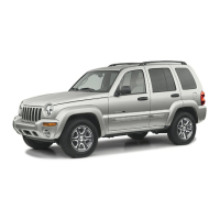
(4) On the rear main cap, apply Mopart Gasket
Maker sealer on both sides of cylinder block as
shown in (Fig. 70). The dab of sealer should be 3 mm
(0.125 in.) in diameter.
(5) Apply Mopart Gasket Maker on the rear bear-
ing cap. The bead should be 2.3 mm (0.09 in.) in
diameter. DO NOT apply sealer to the lip of the seal.
(6) Install the main bearing cap(s) and lower
insert(s).
(7) Tighten the bolts of caps 1, 2, 4, 5, 6, and 7 to
54 N·m (40 ft. lbs.) torque. Now tighten these bolts to
95 N·m (70 ft. lbs.) torque. Finally, tighten these
bolts to 108 N·m (80 ft. lbs.) torque.
(8) Push the crankshaft forward and backward.
Load the crankshaft front or rear and tighten cap
bolt No.3 to 54 N·m (40 ft. lbs.) torque. Then tighten
to 95 N·m (70 ft. lbs.) torque and finally tighten to
108 N·m (80 ft. lbs.) torque.
(9) Rotate the crankshaft after tightening each
main bearing cap to ensure the crankshaft rotates
freely.
(10)
Check crankshaft end play. Crankshaft end
play is controlled by the thrust bearing which is
flange and installed at the No.2 main bearing position.
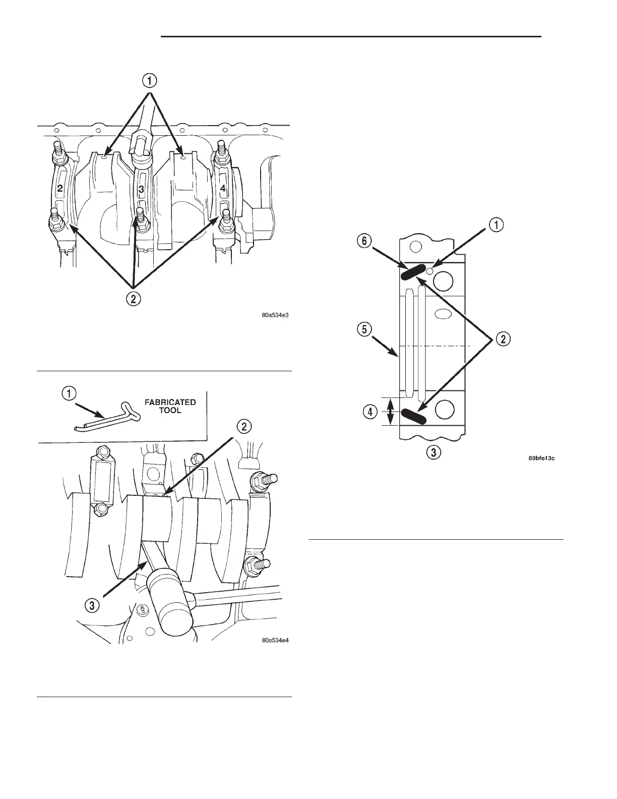
Fig. 68 Removing Main Bearing Caps and Lower
Inserts
1 – CONNECTING ROD JOURNAL
2 – MAIN BEARING CAPS
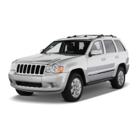
Fig. 69 Removing Upper Inserts
1 – COTTER PIN
2 – BEARING INSERT
3 – TONGUE DEPRESSOR
Fig. 70 Location of Sealer
1 – DOWEL
2 – SEALER LOCATIONS
3 – CYLINDER BLOCK
4 – HALFWAY BETWEEN
5 – REAR FACE OF CYLINDER BLOCK
6 – 3mm (0.125 in.)
9 - 106 4.0L ENGINE XJ
REMOVAL AND INSTALLATION (Continued)






 To Next Page