(8) Remove the O-ring between the worm shaft
and the stub shaft.
ASSEMBLY
NOTE: Clean and dry all components, then lubri-
cate with power steering fluid.
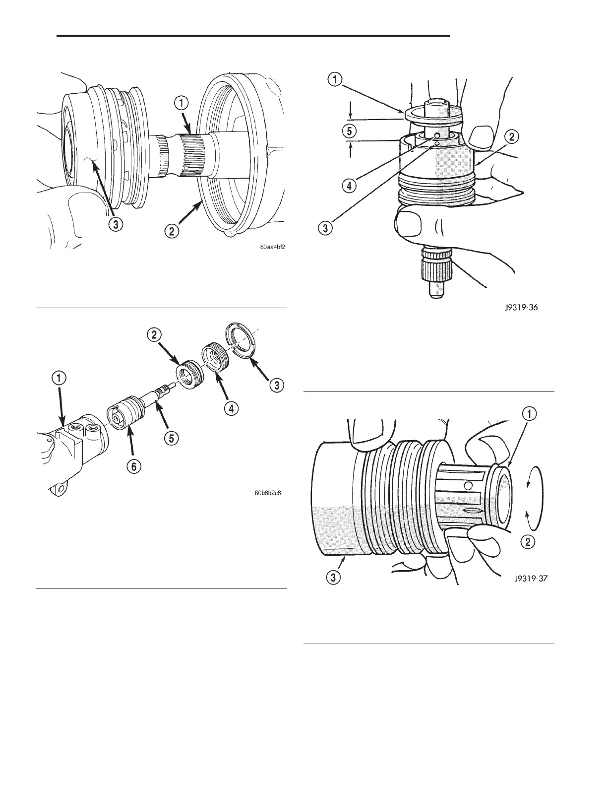
(1) Install spool valve spool O-ring.
(2) Install spool valve in valve body by pushing
and rotating. Hole in spool valve for stub shaft pin
must be accessible from opposite end of valve body.
(3) Install stub shaft in valve spool and engage
locating pin on stub shaft into spool valve hole (Fig.
14).
NOTE: Notch in stub shaft cap must fully engage
valve body pin and seat against valve body shoul-
der.
Fig. 9 Thrust Support Assembly
1 – STUB SHAFT
2 – HOUSING
3 – THRUST SUPPORT ASSEMBLY
Fig. 10 Valve Assembly With Stub Shaft
1 – GEAR
2 – THRUST SUPPORT
3 – LOCK NUT
4 – ADJUSTER NUT
5 – STUB SHAFT
6 – VALVE ASSEMBLY
Fig. 11 Stub Shaft
1 – STUB SHAFT
2 – VALVE BODY
3 – HOLE IN SPOOL
4 – SHAFT PIN
5 – 6mm (1/4”)
Fig. 12 Spool Valve
1 – SPOOL VALVE
2 – ROTATE VALVE TO REMOVE
3 – VALVE BODY
XJ STEERING 19 - 15
DISASSEMBLY AND ASSEMBLY (Continued)










 To Next Page