(12) Remove the adjuster lock nut and adjuster
nut from the stub shaft.
(13) Pull the stub shaft with the spool valve and
thrust support assembly out of the housing.
(14) Remove the worm shaft from the housing
(Fig. 20).
ASSEMBLY
NOTE: Clean and dry all components and lubricate
with power steering fluid.
(1) Check for scores, nicks or burrs on the rack
piston finished surface. Slight wear is normal on the
worm gear surfaces.
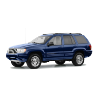
Fig. 16 Rack Piston End Plug
1 – EXTENSION
2 – END PLUG
3 – RACK PISTON
4 – RATCHET
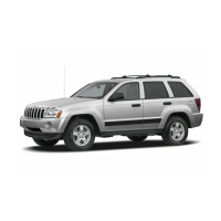
Fig. 17 Rack Piston with Arbor
1 – RACK PISTON
2 – SPECIAL TOOL C-4175
Fig. 18 Rack Piston
1 – CLAMP
2 – BALLS
3 – RACK PISTON
4 – BALL GUIDE
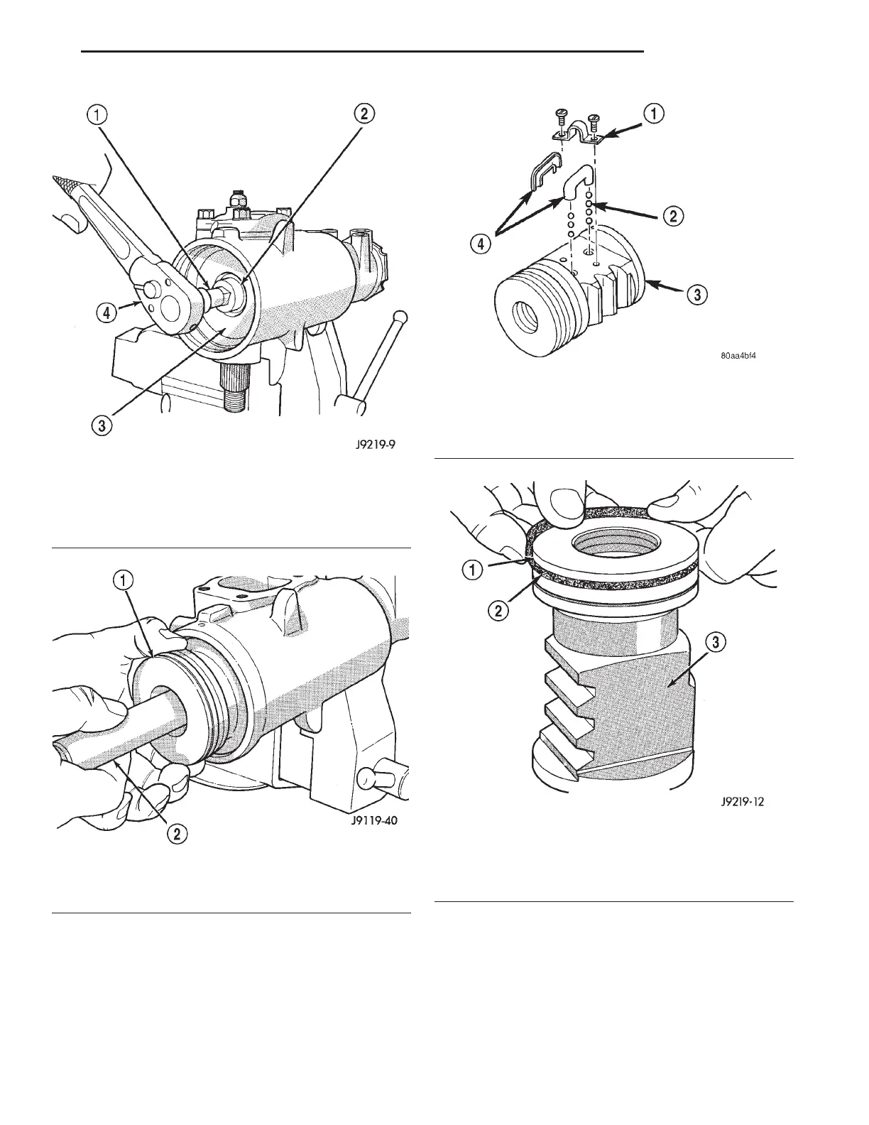
Fig. 19 Rack Piston Teflon Ring and O-Ring
1 – TEFLON SEAL
2 – BACK-UP O-RING MUST BE INSTALLED UNDER PISTON
RING
3 – RACK PISTON NUT
XJ STEERING 19 - 17
DISASSEMBLY AND ASSEMBLY (Continued)