SynMag 2600/3100/3600/4100/5100 7 Operation
BA-0006 • 2020-02-08 EN - 15
7Operation
7.1 Control elements
SynMag 2600/3100
SynMag 3600/4100/5100
• Only qualified personnel are permitted to perform work on the device or system.
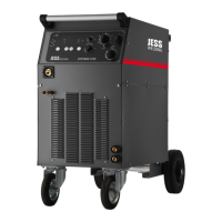
Fig. 12 SynMag 2600/3100 control panel
A Spot welding time knob
B Overheating LED indicator
C WF speed knob
D 2-step/4-step selector
E Welding voltage selector
switch
F Main switch
G Button for displaying the
programme number
H Button for displaying the material
thickness
I Change-over button:
voltage/WF speed (option)
J Indicator:
welding voltage/WF speed (option)
K Indicator:
welding current set/hold (option)
L Indicator:
programme number/material
thickness
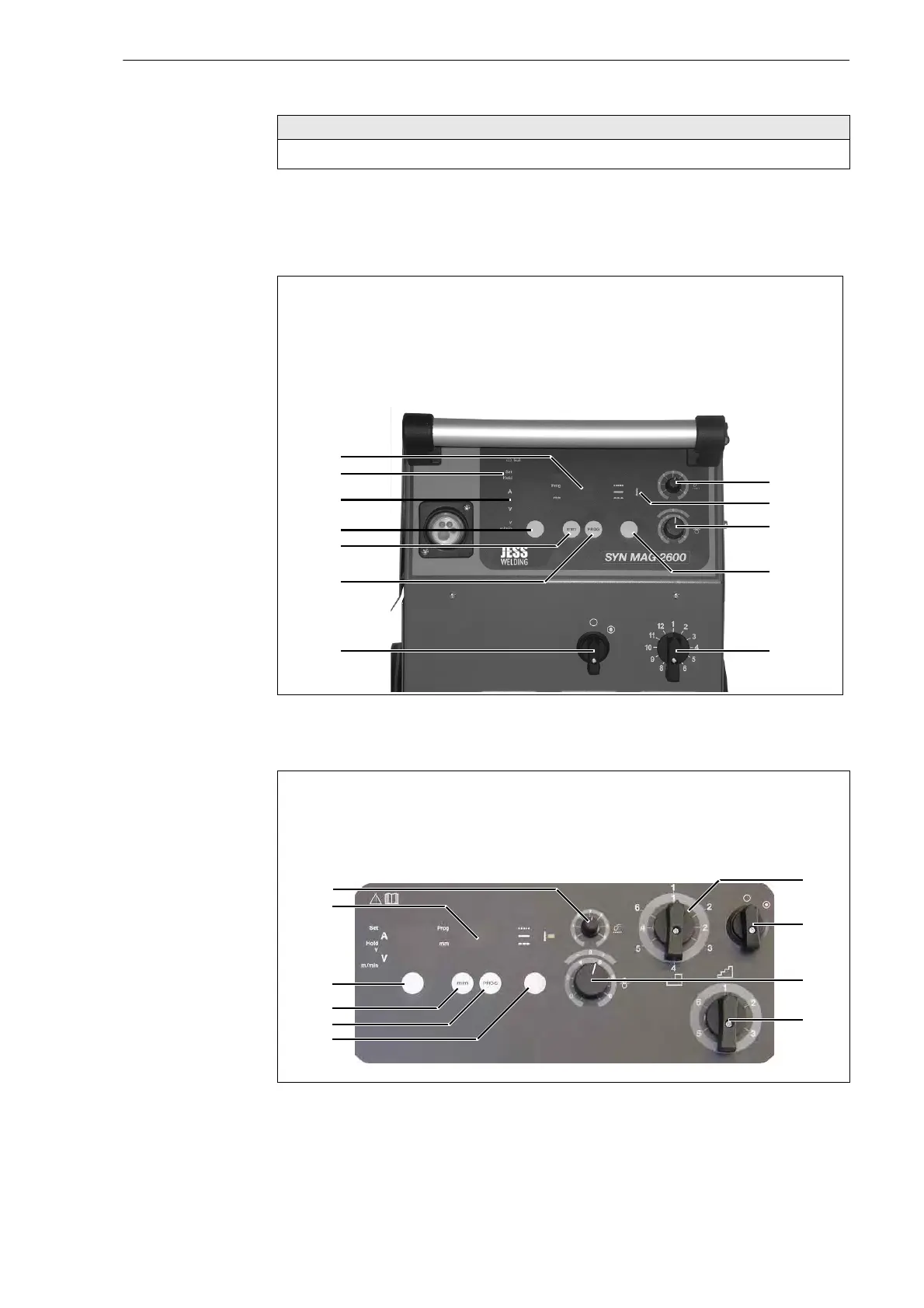
Fig. 13 SynMag 3600/4100/5100 control panel
A General voltage selector switch
B Main switch
C WF speed knob
D Precise voltage selector switch
E 2-step/4-step/spot welding
selector
F Button for displaying the
programme number
G Button for displaying set values
H Change-over button:
voltage/WF speed
I Indicator: programme number/
material thickness
J Spot welding time knob