ASSEMBLING
SWITCH
TO
SAW
CABINET
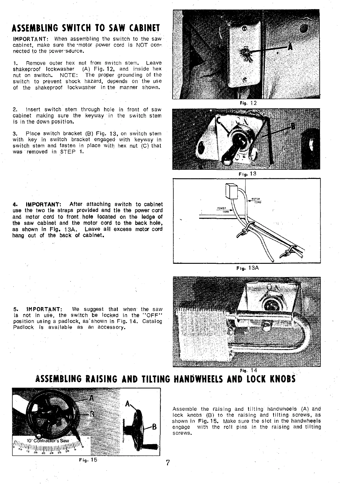
IMPORTANT:
When
assembling the
switch
to
the saw
cabinet
1
make sure the ·motor power cord is NOT
conM
nected to the power·Murce.
L
Remove outer hex nut from
switch
stem. Leave
shakeproof lockwasher (A)
Fig.
12,
and
inside
hex
nut
on
switch.
NOTE: The proper grounding of the
switch
to
prevent shock hazard, depends
on
the use
of the shakeproof lockwasher
in
the manner shown.
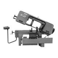
2. lnsert
switch
stem through hole
in
front of saw
cabinet making sure the keyway in the
switch
stem
is in the down
position.
3. Place
switch
bracket
(B)
Fig.
13,
on
switch
stem
with
key in
switch
bracket engaged
with
keyway in
switch
stem
and
fasten in place with hex nul (C)
thal
was removed in
STEP
1.
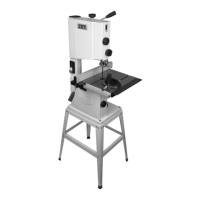
4. IMPORTANT:
Alter
attachlng
switch
to
cabinet
use the two
tle
straps provided and
tle
the power cord
and motor cord
to
front hole located
on
the ledge of
the saw cabinet
and
the motor cord
to
the back hole,
as shown ln
Fig.
13A.
Leave
ali
excess motor cord
hang out
of
the back of
cabinet.
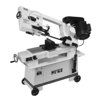
5.
IMPORTANT:
We
suggest
thal
when the saw
i.s
not in use, the
switch
be
locked in the
"OFF"
position
using a padlock, as·shown in
Fig.
14.
Catalog
Padlock is
available
as
an
accessory.
Fig.
13
Fig.
13A
fig.
ASSEMBLING
RAtSING
AND
TILTING
HAN~WHEELS
AND
LOCK
KNOBS
7
Assemble the
raising
and
tilting
handwheels (A) and
lock knobs (B)
to
the
raising
and
tilting
screws, as
shawn in
Fig.
15.
Make sure the
slot
in the handwheels
enga9e with the
roll
pins. in the
raising
and
tilting
screws.