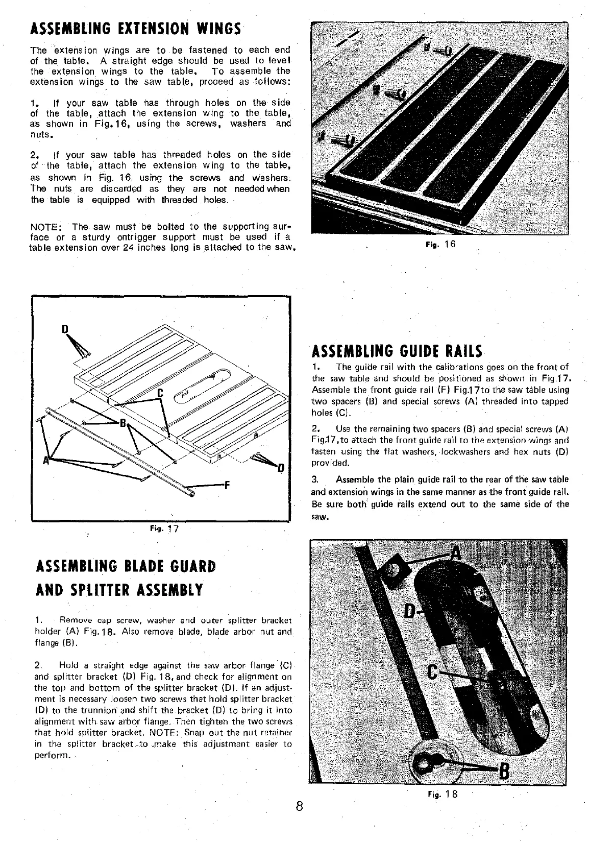
ASSEMBUNG
EXTENSION
WINGS
The extension wings are
to
be
fastened to each end
of the _table. A
straight
edge should
be
usad
ta
leve!
the extension wings
to
the
table,
To
assemble
the
extension wings
to
the saw
table,
proceed as
follows:
1.
If y our saw table has through hales
on
the s ide
of the table,
attach
the extension
wing
ta
the
table,
as shawn in
Fig.16,
using the
screws,
washers and
nuls.
2. If your saw table has
thr~aded
hales
on
the
side
of
the table, attach the
extension
wing
ta
the table,
as shawn in
Fig.
16, using the screws and washers.
The nuts are discarded as they are not needed when
the table
is
equipped with threaded hales.
NOTE:
The saw must
be
bolted
to
the supporting
sur-
face or a sturdy ontrigger support must
be
used
if
a
table extension over
24
inches long is
_attached
to
the
saw.
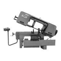
Fig.
17
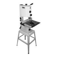
ASSEMBLING
BLADE
GUARD
AND
SPLITTER
ASSEMBLY
1.
Remove
cap
screw,
washer
and
outer
splitter
bracket
helder (A) Fig.
18.
Also
remove
bi
ade,
blade arbor nut
and
flan
ge
(B),
2.
Hold a straight
edge
against the
saw
arbor flange
(C)
and
splitter bracket (D) Fig.
18,
and
check
for
alignment
on
the top
and
bottom
of
the splitter bracket
(0).
If
an
adjust-
ment
is
necessary loosen
two
screws
that
hold
splitter
bracket
(D)
ta
the trunnion
and
shift the bracket (D)
ta
bring
it
into
alignment
with- saw
arbor
flange.
Then
tighten
the
two
screws
that
hold
splitter
bracket.
NOTE:
Snap
out
the
nut
retainer
in
the
splitter
bracket
_
..
to
-~make
this·
adjustment
easier
to
perform.
8
Fig.
16
ASSEMBLING
GUIDE
RAILS
1.
The
guide rail
with
the
calibrations
goes
on
the
front
of
the
saw
table
and
should
be
positioned
as
shawn
in
Fig.17.
Assemble
the
front
guide rail (F) Fig.17to the
saw
tàble
using
two
spacers
(B)
and
special
screws
(A) threaded into tapped
hales (C).
2.
Use
the
remaining
two
spacers (B)
and
special screws (A)
Fig.17,
to
attach
the
front
guide
rqil
to
the
extension
wiilgs
and
fasten
using
the
flat
washers, lockwashers
and
hex
nuts
(D)
provided.
3.
Assemble
the plain guide rail
to
the
rear
of
the
saw
table
and
extensioÎl wings in
the
same
manner
as
the
front-guide·rail.
Be
sure
bath' guide rails extend
out
ta
the
same
side
of the
saw.
Fig. 1 8