11
2. Loosen the lock knob (A) and slide the
cutterhead guard (B, C) to clear the table.
3. Slide the fence assembly back (H, E) as far
as it will go, or remove it from the machine
entirely.
4. Rotate the cutterhead to avoid knife
interference.
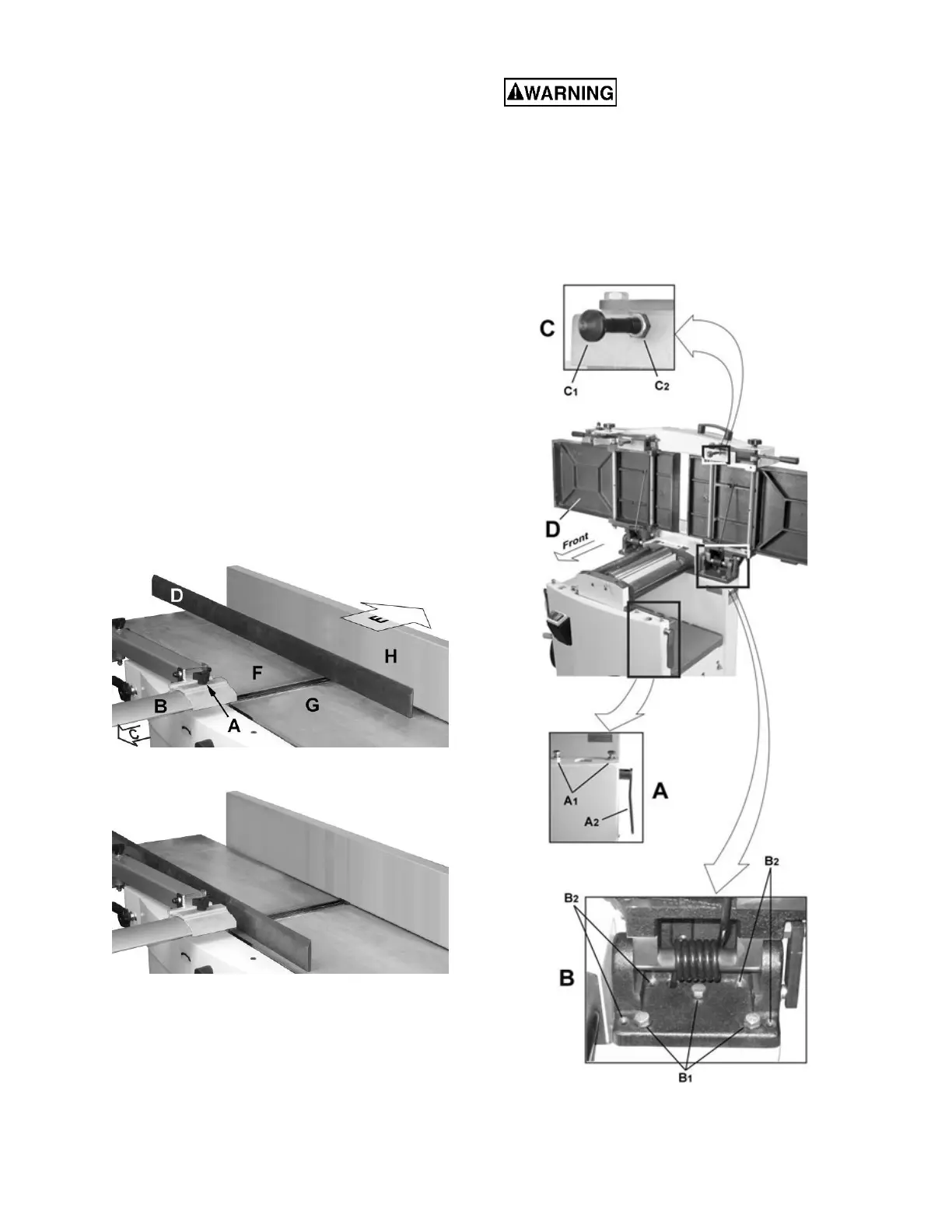
5. Place a straight edge (D) across the back of
the outfeed table (F) and extending over the
infeed table (G). Note the position of the
infeed table (G). Note the position of the
straight edge in Figure 8 with respect to the
fence (H).
6. Raise the infeed table (G) until it contacts
the straight edge (D).
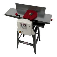
The straight edge should lie level across both
tables. Move the straight edge to the front of the
outfeed table as shown in Figure 9 and perform
the same test.
If the straight edge does not lie level, the front or
back of one of the tables must be adjusted to
make the tables coplanar. Proceed as described
in Performing the coplanar alignment below.
Figure 8
Figure 9
Performing the coplanar alignment
If alignment is required as determined in the
previous section, proceed as follows:
Disconnect machine from
power source before making any
adjustments. Failure to comply may cause
serious injury.
1. Disconnect power from machine.
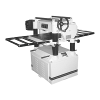
2. Unlock both cabinet lock handles (A2,Fig.
10).
3. Raise the table (D) fully upright.
Figure 10