15
Cutterhead Drive Belt Replacement
4. Loosen four motor mount screws (L). Lift the
motor and rest it in the horizontal slot side of
the motor mount opening. This will create a
slack in the cutterhead drive belt (F).
5. Remove the cutterhead drive belt (F) from
around the cutterhead pulley (E) and motor
pulley (M).
6. If the feed-roller belt (K) is to be replaced,
continue. Otherwise proceed to step 10.
Feed-roller Belt Replacement
Note: If the feed-roller belt is to be replaced,
steps 1–5 must be performed to remove the
cutterhead drive belt before the feed-roller belt
can be replaced.
7. Place the power feed handle (J) in the down
(off/disengaged) position, which provides
belt slack for the next step.
8. Remove the feed-roller belt (G) from around
the feed-roller pulley (K) and motor pulley
(M).
9. Loop the new belt around the smaller (inner)
motor pulley (M) and feed-roller pulley (K).
Note: The lower stretch of the feed-roller
pulley must be positioned between the belt-
brake plates (N).
Concluding Steps
10. Replace the cutterhead drive belt (F) by
looping it around the cutterhead pulley (E),
then the larger (outside) motor pulley (M)
11. Slide the motor so that the mounting screws
(L) rest back in the vertical slot openings,
then tighten the mounting screws.
12. Replace the lower back panel (P) and
secure with four button head socket screws
(O).
13. Replace the upper back panel (D) and
secure with two button head socket screws
(C).
14. Replace the jointer fence assembly (A) and
secure with two lock handle assemblies (B).
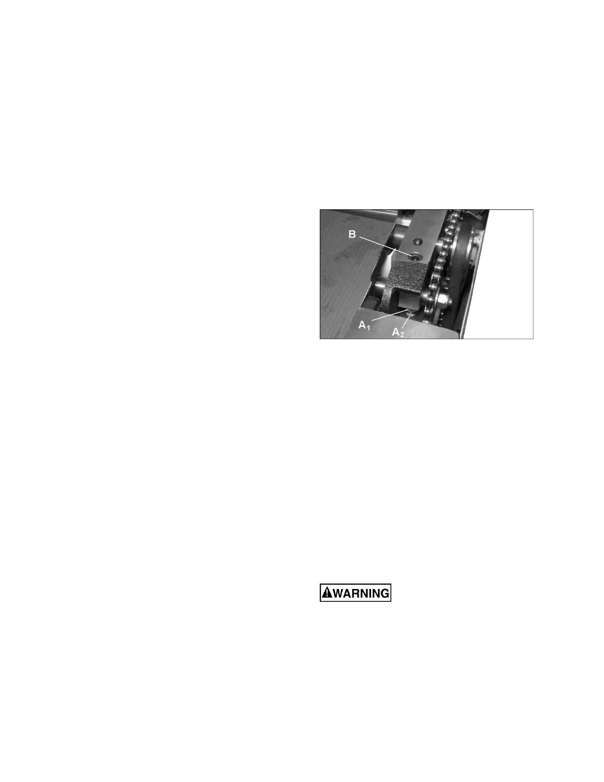
10.8 Feed roller height adjustment
Refer to Figure 15.
The height of the infeed and outfeed rollers has
been set by the manufacturer for planing
operations. If this setting should ever need
adjustment, it is done using the screw and nut
(A
1
,A
2
, Figure 15) at each end of the rollers.
1. Disconnect machine from power source.
2. Remove the covers from front and back of
the machine.
3. At the back, remove the chain and sprockets
from their shafts.
4. Loosen the hex nut (A
1
) and rotate the
screw (A
2
) as needed to raise or lower that
end of the roller. NOTE: Feed rollers must
remain parallel to the table, and about 1/32”
below the cutting arc of the knives or knife
inserts.
5. Adjust any of the four screw/nut assemblies
as needed.
Figure 15
6. Use a gauge on the planer table to verify the
height of the rollers in relation to the
cutterhead.
7. When settings are correct, tighten the hex
nuts (A
1
) up against the casting.
8. Make test cuts to verify the setting.
10.9 Feed roller pressure adjustment
Refer to Figure 15.
The pressure of the feed rollers against the
workpiece during planing operations is
maintained by spring tension. To adjust this
tension, turn the socket head screw (B, Figure
15), clockwise to increase pressure,
counterclockwise to decrease pressure.
10.10 Planer table adjustment
Disconnect machine from
power source before making any
adjustments. Failure to comply may cause
serious injury.
Checking Planer Table Parallel to Cutterhead
The planer table is set parallel to the cutterhead
by the manufacturer and no further adjustment
should be needed. If your machine is planing a
taper, first check to see if the knives are properly
adjusted in the cutterhead (see sect. 10.3,