13
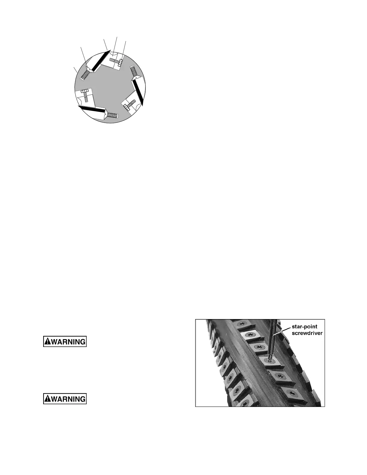
Figure 12
6. Note the position of the knife blade with
respect to the straightedge, then move the
straightedge to the other side of the table
and again note the position of the knife
blade with respect to the straight-edge.
Blade number one must be at the same
height at each end and must also be at the
same height as the outfeed table (bottom of
straightedge). If this is not the case,
adjustment is required as follows:
7. Slightly loosen five gib lock screws (A) by
turning into the lock bar (B), clockwise as
viewed from the infeed table (G).
8. Adjust the blade height by turning jack
screws (D) upon which the blades rest. To
lower the blade, turn the screw clockwise.
To raise, turn the screw counter-clockwise.
9. When the blade is at the proper height,
alternately tighten the five gib lock screws
(A).
Repeat steps 4-9 for blades two and three.
10.4 Replacing cutterhead knives
(straight knives only)
Disconnect machine from
power source before making any
adjustments. Failure to comply may cause
serious injury.
1. Disconnect machine from the power source.
2. Remove the cutterhead guard (B, Fig. 8).
Cutterhead knives are
dangerously sharp. Use extreme caution
when inspecting, removing, sharpening, or
replacing knives into the cutterhead. Failure
to comply may cause serious injury.
Refer to Figures 11 and 12:
3. Turn all five screws (A) into the lock bar (B)
by turning in a clockwise direction as viewed
from the infeed table (G).
4. Carefully remove the cutter knife (C) and
lock bar (B).
5. Repeat for remaining two knives.
6. Thoroughly clean all surfaces of the
cutterhead, knife slots and lock bars of any
dust or debris.
7. Insert replacement knife (C) into the knife
slot, making sure it faces the proper
direction.
8. Insert lock bar (B) and tighten just enough to
hold in place.
9. Repeat for other two blades.
The knives must now be adjusted as described
in sect. 10.3, Setting cutterhead knives.
10.5 Replacing or rotating knife
inserts (helical cutterhead only)
The knife inserts on the model JJP-12HH are
four-sided. When dull, simply remove each
insert, rotate it 90° for a fresh edge, and re-
install it.
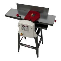
Use the provided star point screwdriver to
remove the knife insert screw. See Figure 13. It
is advisable to rotate all inserts at the same time
to maintain consistent cutting. However, if one or
more knife inserts develops a nick, rotate only
those inserts affected.
Each knife insert has an etched reference mark
to keep track of the rotations.
An extra set of 5 knife inserts and knife insert
screws are included with your JJP-12HH.
Figure 13
(Model JJP-12HH only)
A
B
C
D
E