14
IMPORTANT: When removing or rotating
inserts, clean saw dust from the screw, the
insert, and the cutterhead platform. Dust
accumulation between these elements can
prevent the insert from seating properly, and
may affect the quality of the cut.
Before installing each screw, lightly coat the
screw threads with machine oil and wipe off any
excess.
Securely tighten each screw which holds the
knife inserts before operating the planer. Knife
inserts should be torqued to approximately 50 to
55 inch-pounds.
Make sure all knife insert
screws are tightened securely. Loose inserts
can be propelled at high speed from a
rotating cutterhead, causing injury.
10.6 Jointer table lock handle
adjustment
Refer to Figure 10 on page 12:
For best performance, the jointer table lock
handles (A
2
) should be approximately in the fully
down position when in the locked position. If
adjustment is required:
1. Disconnect machine from power source.
2. Unlock the lock handles (A
2
) and raise the
table to the upright position.
3. Loosen locking nut (C
2
) with an 18mm
wrench.
4. Adjust the table locking shaft (C
1
) in
increments of 1/4 turns or less. Turn
clockwise to tighten the lock handle
performance and counterclockwise to
loosen.
5. Tighten the locking nut (C
2
).
6. Test the locking function and repeat if
necessary.
10.7 Belt replacement
Disconnect machine from
power source before making any
adjustments. Failure to comply may cause
serious injury.
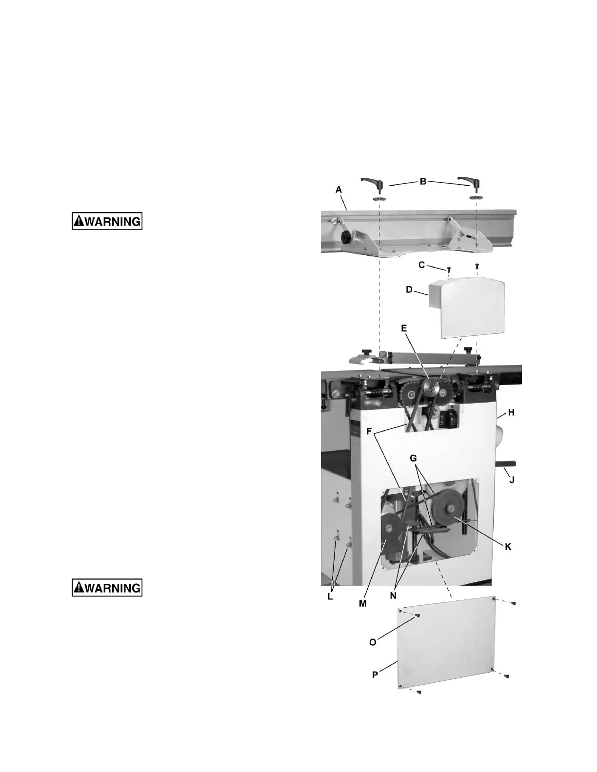
Refer to Figure 14.
Preparation
To replace the cutterhead drive belt and/or the
planer feed-roller belt, the jointer fence
assembly and two back panels must first be
removed as described below. A 4mm hex
wrench and two 13mm wrenches are required.
1. Remove the jointer fence assembly (A,
Figure 14) by first loosening and removing
two lock handle assemblies (B).
2. Remove two button head socket screws (C)
and upper back panel (D).
3. Remove four button head socket screws (O)
and lower back panel (P).
Figure 14