Tertiary Air Tube Removal and Lower V Board Bafe Removal
The sequence for easy removal of the air tubes and lower V board bafes are thus:-
First remove the front tertiary air tube closest to the door of the re.
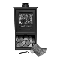
To remove the tube, slacken the 8mm bolt using the 13mm spanner provided. Once the bolt is slack then the
cam catch can be rotated slightly so that the locator comes away from the tube hole releasing the tube. There is
no need to remove the 8mm bolt completely. It is easier for reassembly to just leave it loose.
Once this has been carried out then the tube can be slid across so that one end is released from the side
chamber to drop down allowing space to pull it out of the other side of the chamber.
Next slide forward the V board bafes over the rear tube and drop their front edge down and remove them from
the re. Note their orientation as they are longer along one edge.
Finally remove the rear tube in the same manner as the front tube.
Replacement is the reverse procedure.
First t the Rear Tube, then the lower V boards and then the Front Tube.
CAUTION
Ensure that the cam catch locator is positioned in the tube hole when the bolt is tightened to trap the tube from
sliding out and to ensure that the tertiary air ports are in their correct position within the re.
Ensure that the V board bafes are tted the correct way around.
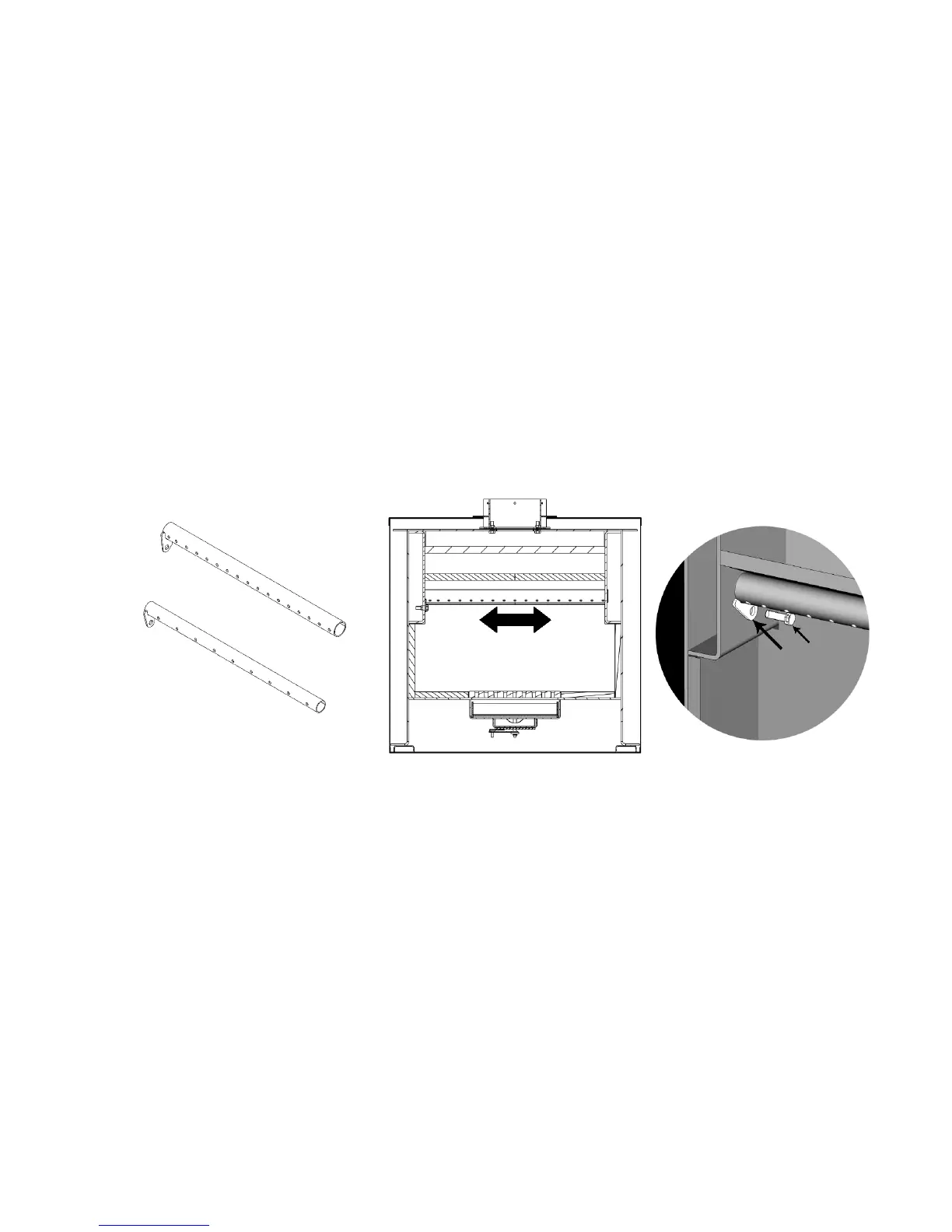
Rear tertiary air tube
Front and back tertiary tubes are
designed to slide across to be
released from side chambers
Front tertiary air tube
Cam Catch
Cam Catch
Cam Catch
8mm bolt
Upper V Board Bafe Removal
Above the lower bafes is xed an upper bafe. To remove this, rst remove the tertiary air tubes and the lower
V board bafes. Once this has been carried out then the upper V board bafe can be removed.
The upper V board bafe is held in place by a clamp that is xed at the front top of the inner rebox. The clamp
is held in place by a single screw. The back of the upper board is held in a recess at the rear of the rebox. Thus
the board is trapped between the clamp and the rear of the box.
To remove the V board upper bafe rst remove the screw that holds the clamp in place. Then, pull the board
foreword out of the rear recess and lower the board down. Care should be taken to hold the board in place as
the clamp is removed so that the board does not drop down and break.
At this point for the purposes of tting the re the remaining V boards and cast bottom grate can remain in
position. However care should be taken when removing and replacing the ue adaptor bolts so that none of the
internal parts become damaged.
If required then the remaining components can be removed for greater access.
15