Outer Firebox Fitting
The box can be sealed to the opening using the insulation supplied, or similar insulating material.
Place the outer rebox in front of the prepared opening. Wrap the sides and back of the re with the insulation
and hold this in place with tape. Insulation should also be placed across the top of the outer rebox in front of the
ue adaptor to allow for expansion and contraction and to protect the wall above from excess heat.
Slide the outer rebox into position in the prepared recess, taking care not to snag the insulation on the sides/
top of the opening.
Larger voids around the box can be lled with a non combustible insulation.
Once in position x the outer box by drilling through the xing holes located in the base and screw/bolt to the
base of the opening using suitable xings.
Where the opening is signicantly higher than the outer rebox, the space may be lled by brickwork. Place
a layer of insulation beneath the bricks to provide an expansion joint on top of the outer rebox in front of the
adaptor to allow for expansion and contraction and to protect the wall above from excess heat. If more than three
or four courses of brick are needed, these should be supported on a lintel or steel bar between the jambs.
Where slate or marble slips are used, these should be placed behind to form a sliding contact and thus allow for
the expansion of the re. Do not allow slips, marble, plaster or brickwork etc to abut the edge of the frame or to
have direct contact with the rebox as expansion of the re may cause them to crack. Use a strip of insulation
as an expansion joint where necessary.
Note:- If an external primary air supply is to be used then the knockout in the rear of the outer box must be rst
removed before tting the outer box into the opening. Then, depending on the route of the exible pipe a hole or
clearance needs to be made behind the outer box to accommodate the pipe routing it to external air.
External Air Supply Fitting
The primary air can be taken from the room or alternatively it can come from an external source from outside
the building.
If taken from the room then air ducts are required to the room, as the re will take its primary air from the chamber
around the re that is fed by air from the room. See section on Air supply for details.
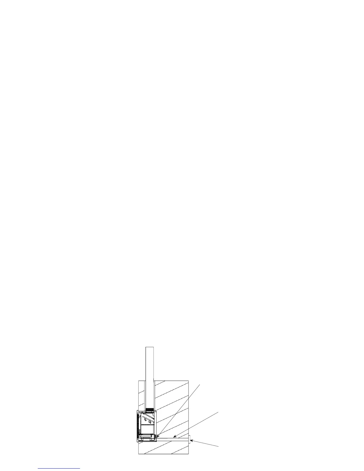
If air is required to be brought in from an external source then rst the knockout at the rear of the outer box
should be removed by careful removal with a hammer.
This will allow a exible pipe to be pushed through the back of the outer box and over the air chamber pipe
attached to the inner rebox.
The exible pipe should be held in place with the circular clamp supplied.
It is usually easier to t the exible pipe to the inner rebox rst then slide the exible pipe through the knockout
hole in the outer box as the inner box is being slid into place. Then at this point the ex can be fed through any
holes in the wall or oor to an external air source. An open grille maybe attached to the end of the exible pipe
to stop debris from blocking the pipe. Ensure that the grille does not restrict the air supply. The air requirements
are listed in the data table on page 5.
18
Flexi Pipe
Clamp
Grille