7
TwinForce™ Series Waterblast Unit
COMPONENT IDENTIFICATION
Before operating the unit it is necessary to fully understand each component and how it functions.
Following is a brief description of the main components of the TwinForce unit.
Engine
The engine is the source of power to drive
the pump. Available engine options provide a
power range of 325-400 HP (243-298 kW) in
single unit conguration or 650-800 HP (485-
597 kW) in dual unit conguration.
Clutch and PTO
The clutch, through use of a lever on top, pro-
vides the means to engage and disengage the
clutch. When engaged, power is transmitted
from the engine to the pump via the power
take off (PTO) and belt drive. The PTO contains a
shaft that rotates on bearings
Belt Drive
The belt drive is driven by the PTO. A pulley is
mounted on the PTO shaft and, when engaged,
drives the other pulley to operate the pump.
UNx™ Pump
The UNx pump uses the power from the engine
to pressurize the source water into high pres-
sure output. The pump is separated into two
sections, the power end and the uid end.
The power end contains the components that
drive the pump. It is also referred to as the
“crank end” because it contains a crankshaft.
The uid end contains the components that de-
termine the output pressure of the pump. The
operator may change the output pressure and
ow of the pump by changing the components
in the uid end. The uid end is also referred
to as the “wet” end as this is where the water
travels in and out of the pump.
Refer to the pressure specic catalogs (15K,
20K and 40K) for detailed exploded views and
component part numbers for the uid and
power ends. The catalogs are available at the
following website:
https://waterblast.com/new-catalogs
Inlet Water Filtration
Each pump has an associated dual water
ltration package. Inlet water travels from the
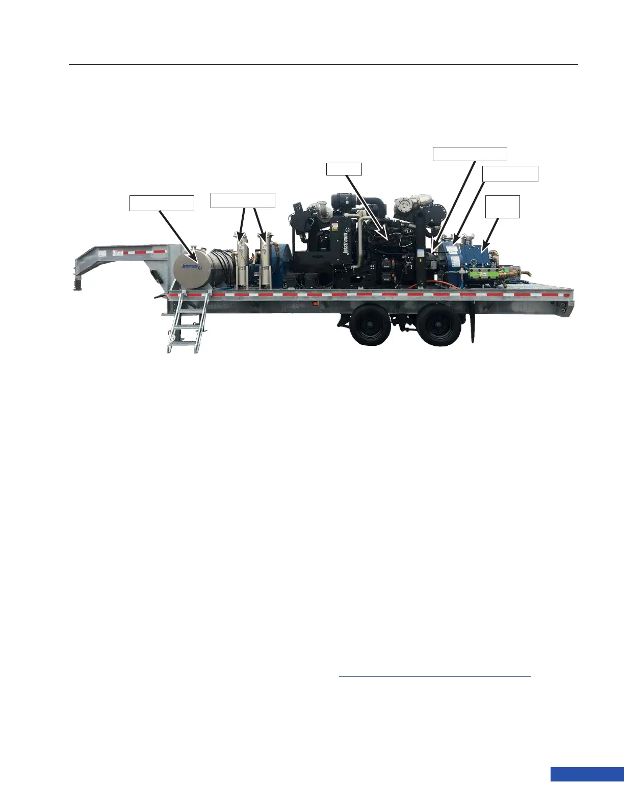
Figure 8: TwinForce Series Waterblast Unit
Engine
UNx
Pump
Clutch & PTO
Belt Drive
Fuel Tank
Water Filters