8
Operation Manual
charge pump into the rst lter and then the
second lter in line. A ball valve is tted to the
inlet side of the lter after the charge pump.
This is used when the associated pump will
not be used, but there is water supply due to
use of the opposite triplex pump.
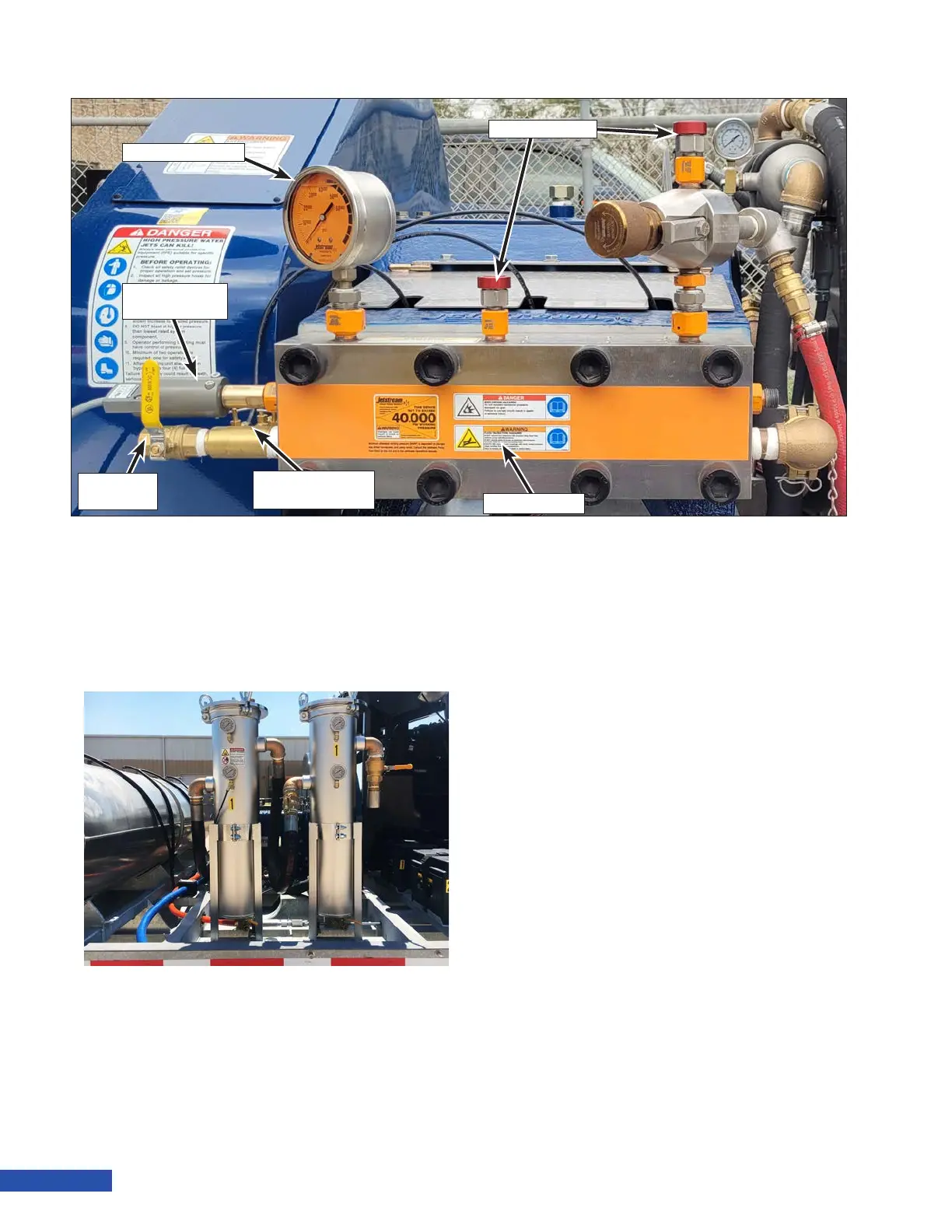
Manifold
The manifold houses many of the components
that make up the uid end of the pump in-
cluding the uni-valves. The three uni-valves
each consist of a suction and discharge valve
combined into one assembly. The valves con-
vert low pressure water to high pressure water.
.
Manifold Drain Valve
The manifold drain valve allows the manifold
to be ushed of contaminants prior to pump
usage. It is also used to purge air during op-
eration start up.
Water Lubrication System
The water lubrication system provides water
to the packing in the pump. The water lubri-
cates and cools for optimum operation of the
pump. The system includes a manifold and
three water lines. Needle valves are present
on manifolds that are pressure fed (all 40K
units). The needle valves control the amount of
ow to each stufng box and must be prop-
erly adjusted during operation. Manifolds that
are not pressure fed have a xed ow. Refer to
“Charge Pump (40K Units)” on page 13 for
more information on pressure fed manifolds.
Pressure Gauge
The liquid lled pressure gauge allows the
operator controlling the pump to monitor the
pressure of the system.
Pressure Gauge
Hydro-Throttle
Switch
Water Lubrication
System
Manifold
Drain Valve
Manifold
Rupture Discs
Figure 9: Pump Components
Figure 10: Water Filter Housings