19
TwinForce™ Series Waterblast Unit
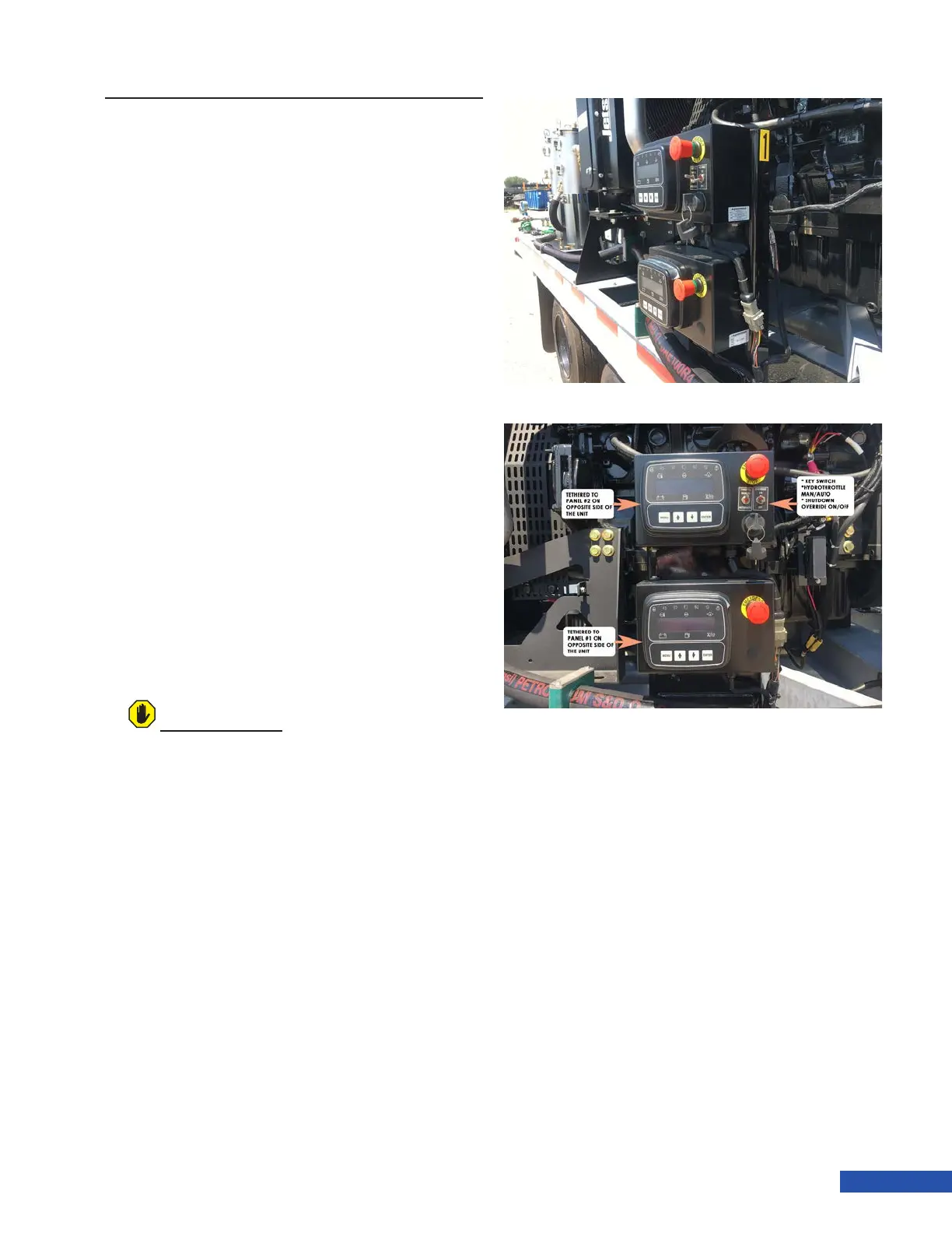
CONTROL PANEL
Twin Force units come equipped with a total of
4 control panels. The associated panels are ei-
ther marked with a “1” or a “2” (Figure 28). Two
control panels are able to control and monitor
a single engine, although only one of each pair
is able to start with key. The “Near Side” Panel
has the key and toggle switches, and the “Far
Side” panel does not have the key and switch-
es. These panels are linked together, but any
parameter that is manually changed in one of
the pair, will need to be also set in the alter-
nate control panel. Detail on accessing menus
and parameters can be found in the control
panel manuals that come with the unit.
Shutdown Override: When switched to
the ON position, the override switch will
ignore the low water level sensor and/or
the differential pressure switch (secondary
lter) and the engine will run without water
at the lters. When switched to the OFF
position, the unit will not start without water
supplied to its associated lters. If no water
is present, the panel will display “Emergency
Stop”.
Throttle Mode: When the switch is in the
Automatic position, the engine will switch
from the predened minimum speed to the
set operating speed as demand from the
pump changes.
When in the Manual position, the throttle
up and throttle down buttons must be used
to change engine speed.
For additional information, see the control
panel operations manual supplied with the
unit.
ATTENTION
Do not operate the unit in override mode. The
override feature is typically used for engine
service.
Figure 28: Main Control Panels