36
Operation Manual
3. Belt Inspection - Inspect the belts for
cracks, damage, glazing or any other
defect. Replace as necessary. Replace the
belts as a set and adjust the new belts as
outlined in “Adjusting Belt Tension” on
page 75.
4. Regular Stufng Box Lubrication Check
- Remove stufng boxes, clean power-
frame bore, lubricate with anti-seize
or petroleum jelly, and replace stufng
boxes.
Winterizing The Unit
Severe damage can result if the waterblast
unit is not protected from freezing condi-
tions. The stufng boxes hold water that can
freeze causing damage to the stufng boxes,
uni-valves, plungers and manifold. To prevent
freezing drain the water from all hoses, charge
pump and tanks, and add anti-freeze to the
stufng boxes.
If the unit is to be idle for any period of time
that would allow freezing in the pump or pip-
ing, utilize the following procedure:
1. Drain the water from the tank.
2. Disconnect the water supply suction line
and high pressure discharge hose from the
manifold.
3. Drain the manifold of water and close the
drain.
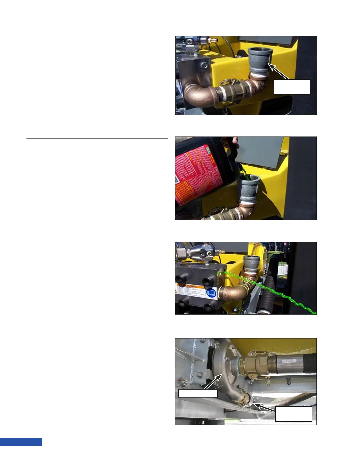
4. Assemble pipe ttings into a funnel as-
sembly as shown in (Figure 44).
5. Install the assembly on the suction side
of the manifold.
6. Pour a glycol based anti-freeze solution
into the funnel as shown in (Figure 45).
Approximately 0.5 gal. (2 L) of anti-freeze
is required.
7. Place the override switch in the ON posi-
tion to bypass the low water shutdown.
8. Before starting the engine, check the area
in the path of the discharge tting on the
manifold. Ensure the area is clear. Anti-
freeze will be discharged from the dis-
charge tting during this procedure.
Funnel
Assembly
Figure 44: Funnel Assembly Installation.
Figure 45: Adding Anti-Frieeze.
Figure 46: Draining the Anti-Freeze.
Discharge
Hose
Charge Pump
Figure 47: Draining the Charge Pump.