11
TwinForce™ Series Waterblast Unit
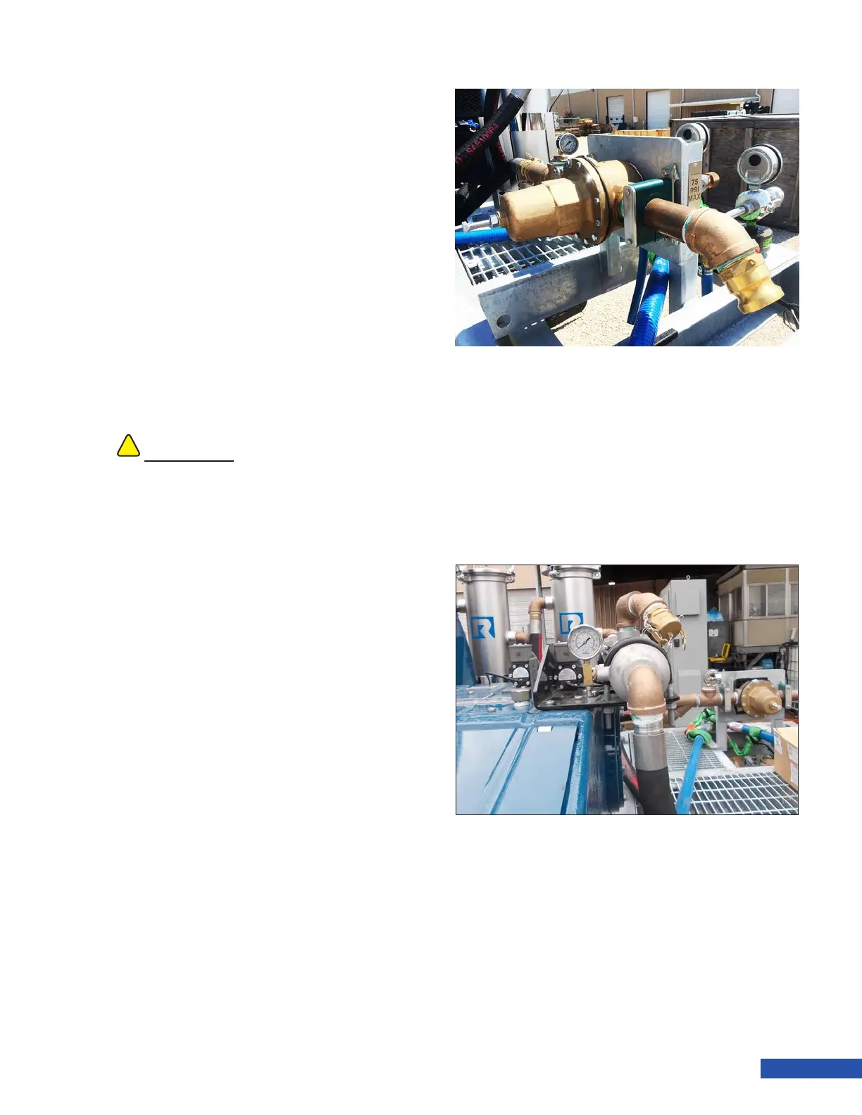
Water Inlet
The inlet water connection (Figure 13) is a 2”
Camlok Nipple. The inlet regulator is adjust-
able and pressure to the uid end should not
exceed 75 psi.
Bypass Drain
The bypass drain is connected to the bypass
valve. Water will drain from the hose onto the
ground during pump operation as explained
in “Secondary Filter (40K Units)” on page
11. This hose can be plumbed to an alter-
nate drain or tank for collection if required. If
bypass drain water needs to be routed to a dif-
ferent location, contact Jetstream engineering
for assistance.
Secondary Filter (40K Units)
A secondary lter (Figure 14) is mounted on
top of the pump for use when operating at
“40K”. The lter is not connected during 15K or
20K operation.
A pressure gauge is mounted on the lter to
monitor pressure in the lter.
A differential pressure switch is mounted
in the lter circuit to monitor proper ow
through the lter. If the lter becomes plugged
and ow is insufcient, the switch will cause
the engine to shut off. “Emergency Stop” will
be displayed on the control panel.
A drain valve is located on the lter cover that
allows the operator to purge air from the lter
at startup.
!!
CAUTION
If a bypass discharge hose is used, the hose
must be properly sized to prevent excessive
backpressure. Excess backpressure can cause
vibration and pulsation in the system leading to
damaged system components.
Figure 13: Water Inlet
Figure 14: Secondary Filter