10
Operation Manual
when operating one or more shut-in devices.
When a gun or other device is disengaged,
the regulator automatically adjusts to shift
the excess ow to a low pressure outlet while
maintaining system pressure. Because shut-in
systems maintain constant system pressure,
the hydro-throttle does not function in these
applications.
Discharge Fitting
The discharge tting allows the connection of
a high pressure hose. High pressure water ex-
its from this tting. On 15K manifolds, a quick
disconnect is recommended to prevent galling
of pipe threads and damage to the manifold.
Supply Couplings
The supply couplings provide a quick method
for attaching the supply hose to the manifold.
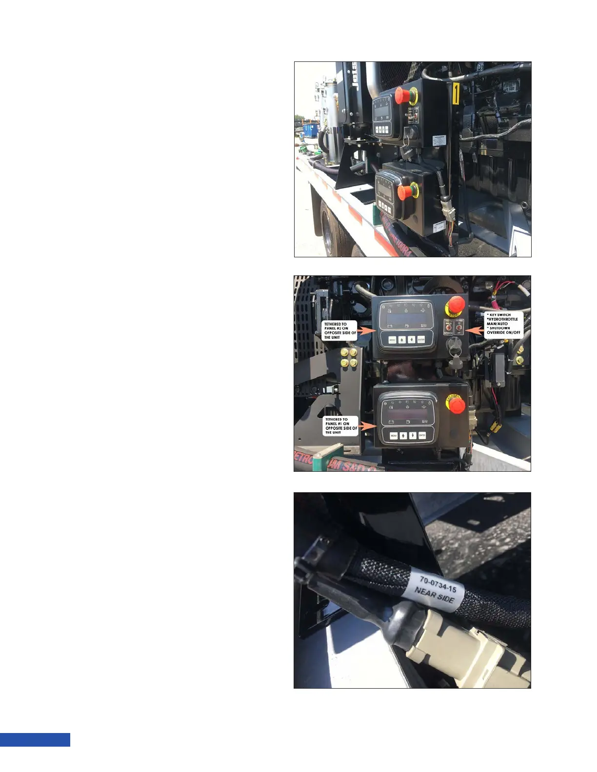
Control Panels
Twin Force units come equipped with a total of
4 control panels. The associated panels are ei-
ther marked with a “1” or a “2” (Figure 12). Two
control panels are able to control and monitor
a single engine, although only one of each pair
is able to start with key. The “Near Side” Panel
has the key and toggle switches, and the “Far
Side” panel does not have the key and switch-
es. These panels are linked together, but any
parameter that is manually changed in one of
the pair, will need to be also set in the alter-
nate control panel. Detail on accessing menus
and parameters can be found in the control
panel manuals that come with the unit.
Each end of the tether cable connecting two
panels for control of the same engine is iden-
tied as “Near Side” or “Far Side”. This desig-
nates which panel that particular end should
connect to.
Figure 12: Control Panels