RL1 User Manual
9
M-RL1-001-01
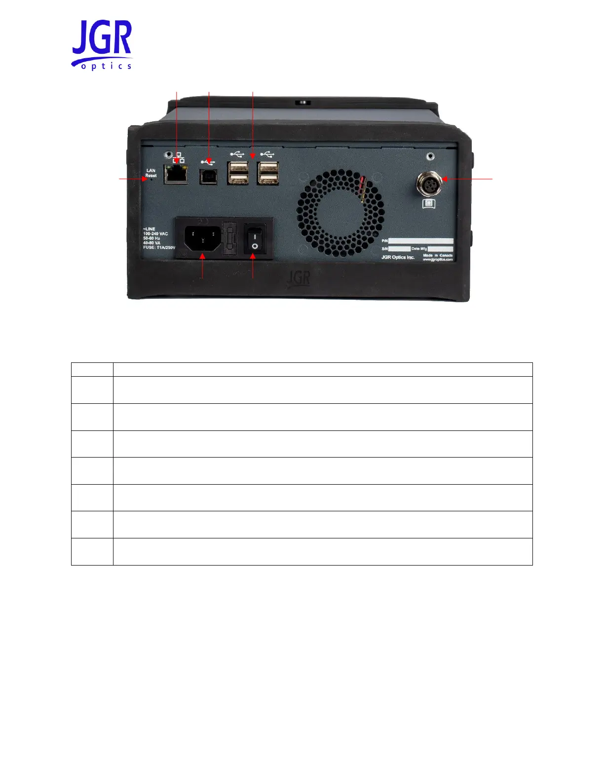
Figure 3: Rear view of an RL1
Table 3: Detailed description of the RL1 rear panel components (see Figure 3)
RD-S Wireless Remote-head Detector
The RL1 comes standard with one RD-S Wireless Remote-head Detector. Additional RD-S detectors can be
paired to an RL1 for more test setup flexibility. They are connected to each other in series. Figure 4 shows
a front view of the RD-S. It uses a wide aperture integrating sphere cavity for maximum uniformity and is
ideal for multifiber assemblies such as MPO or duplex LC. Figure 5 shows the rear of the RD-S (see Table
4 for a detailed description).