SECTION 3 - COMPONENT SERVICING
3-10 – JLG Lift – 3121741
8. With the gas cylinder de-pressurized, loosen,
but do not remove, the four bolts attaching the
gas cylinder mount to the top of the outer mast
section.
9. Check that the mount can be moved up and
down by hand, and there is not a great amount
of pressure on the mount from the gas cylinder.
If OK, remove the bolts from the mount and
remove the mount from the top of the mast.
10. Remove the safety interlock pin cover and pull
the interlock pin out and rotate 90° to lock the
pin in the retracted position.
11. Removing the outer mast/front cover assembly
from the mast.
a. Remove the 14 screws (7 each side) from the
front cover assembly.
12. The belt drive system clamp assembly which
clamps the belt ends, is anchored to the inner
mast section and must be unbolted.
a. The head of the belt clamp mounting bolts
must first be aligned with the access hole in
the flywheel mounting plate on the front of
the mast. (See Figure 3-16.) This is so they can
be kept from turning while removing the
nuts inside the inner mast section.
b. At the top of the mast assembly approxi-
mately 6 in. down on the inside of the inner
mast weldment, remove the two lock nuts
attaching the belt clamp assembly to the
inner mast weldment.
13. Once step 8 and 9 are completed the complete
outer mast front cover and flywheel assembly
can be lifted off the mast assembly for further
disassembly, if required.
14. Remove the mast guide roller from the bottom
front of the mast assembly.
15. Using an assistant, lift the outer mast section off
the inner mast section and set aside for disas-
sembly, if necessary.
16. If necessary, remove the gas cylinder from the
inner mast section. If tight in the mounting hole
on the bottom of the inner mast section, you
may have to tap the cylinder rod with a flat
punch to get it started out of the mounting hole.
17. At the top of the inner mast section carefully pull
the gas cylinder out of the inner mast section.
18. If necessary to remove the drive belt assembly
from the front cover.
a. Compress the spring tensioner enough to
allow the belt to be slid off the lower belt
cog gear.
b. Remove the bolt from the belt guide roller
plate beside the drive gear, this will allow
the belt to be removed from the drive gear
and idler cog gear next to it.
c. The belt and clamp assembly should now be
free from the front cover assembly.
d. If replacing belt, disassemble the belt clamp
assembly and install new belt. (See Figure 3-
17.)
Mast Re-assembly
(Item numbers refer to Figure 3-15.)
Assemble the mast reversing the steps above.
Mast components requiring lubrication, anti-seize com-
pound, or thread locking compound during assembly:
• Thread Locking Compound Required:
• Apply to threads of lanyard attach eyelet. (on item
4)
• Belt tensioner stop - apply to socket head screw
and nut just above the pully block on front panel.
(on item 4)
• Apply to threads of belt guide plate mounting
bolt and nut. (item 9)
• Apply to threads of belt clamp allen head mount-
ing bolts. (item 6)
• Apply to threads of gas strut support bracket mast
bolts. (top of item 3)
• Anti-Seize Compound:
• Apply to threaded stud on belt spring tensioner.
(on item 6)
• Coat the flat facing surface of the three pulleys
and drive gear and the guide plate. (on item 4 and
9)
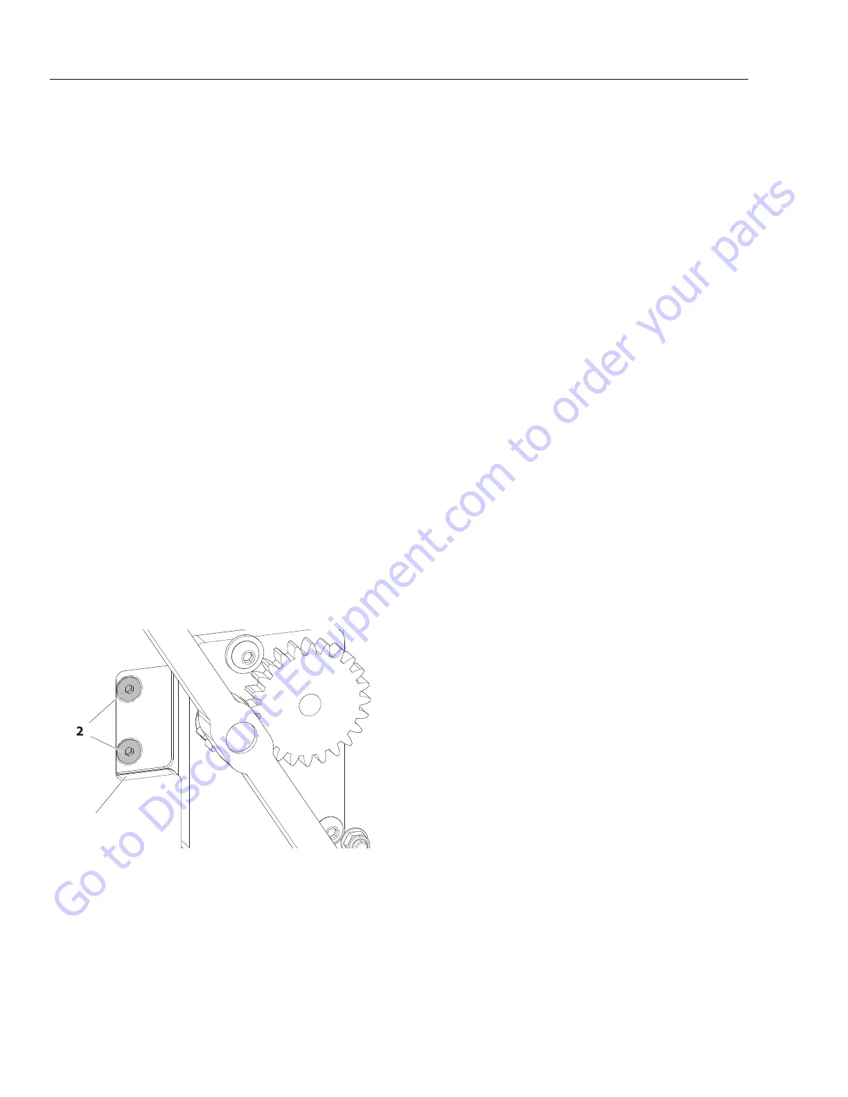
Figure 3-16. Belt Clamp Mounting Bolts - Ecolift
1. Flywheel Plate Access Hole 2. Belt Clamp Mounting Bolts
NOTE: Extend or retract mast assembly to almost stowed position to align with belt
clamp bolt heads.
Go to Discount-Equipment.com to order your parts