SECTION 3 - COMPONENT SERVICING
3121741 – JLG Lift – 3-13
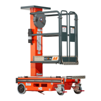
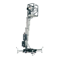
3.8 830P MAST INSTALLATION
(See Figure 3-19.)
The 830P mast is extended using a hydraulic cylinder pres-
surized by a hydraulic pump.
The 830P mid and outer mast sections are removable, the
inner mast section is stationary and is welded to the base
assembly, so therefore not removable.
Mast Disassembly
1. Completely lower the platform to stowed posi-
tion..
2. Remove the tool tray. (See Section 3.2)
3. Remove the platform assembly. (See Section 3.5)
4. Remove the frame cover. (See Section 3.1)
5. Disconnect the positive (+) battery terminal at
the battery.
6. Remove the mast top cap bolts on the sides of
the outer mast section. Carefully pull/pry up on
the top cap to manually extend the hydraulic
cylinder rod.
7. Remove counter sunk hex head screw attaching
the hydraulic cylinder rod to the mast top cap.
Remove the mast top cap and lay aside.
NOTE: It may be necessary to restrain the cylinder rod from
turning when removing the screw attaching it to the
mast top cap. If gripping the rod surface, protect it
from severe damage, grip as close to the bottom of
the top cap as possible, as this area does not retract
into the cylinder barrel.
NOTE: If only removing lift cylinder jump to steps17 and 18
next.
8. Next loosen the lock nuts on all the wear screws
around the base of the outer mast section.
Loosen wear screws until flush with mast inside
surface.
9. Loosen the two slide pads, one each side, at the
top of the mast mid section and slide as far rear-
ward as possible and hand tighten in place.
10. Remove the roller guide at the bottom front of
the outer mast section.
11. The outer mast section weighs approximately 77
lb., using suitable lifting equipment, carefully
and slowly lift the outer mast section off the mid
mast section assembly.
NOTE: In order to slide the mid mast section off of the inner
mast section, the mid mast section must be pushed
rearward to create clearance between the spring
dampening bar stop mounted on the inside of the
lower half of the mid mast section and the spring
dampening assembly mounted three quarters the
way up on the outside of the inner mast section.
12. Loosen the lock nuts on all the wear screws
around the base of the mid mast section. Loosen
wear screws until flush with mast inside surface.
13. Loosen the two slide pads, one each side, at the
top of the inner mast section and slide as far
rearward as possible and hand tighten in place.
14. Remove the roller guide at the bottom front of
the mid mast section.
15. The mid mast section weighs approximately 66
lb., using suitable lifting equipment, carefully
and slowly lift the mid mast section off the inner
mast assembly.
16. If removing the hydraulic cylinder, remove the
access panel at the bottom rear of the mast
assembly. Disconnect and cap the hydraulic line
attached to the bottom of the cylinder.
17. Carefully remove the cylinder from the inner
mast section, protect cylinder rod from damage.
Mast Assembly Notes
(Item numbers refer to Figure 3-19.)
Assemble the mast reversing the steps above.
Mast components requiring lubrication, anti-seize com-
pound, or thread locking compound during assembly:
• Thread Locking Compound Required:
• Apply to threads of fitting on bottom of lift cylin-
der. (item 5)
• Apply to threads of hydraulic line fitting on bot-
tom of lift cylinder. (item 5)
• Apply to threads of mast cap to cylinder rod
screw. (item 4)
• Apply to threads of mast cap to outer mast sec-
tion screws. (item 4)
• Anti-Seize Compound:
• Coat the surface of the spring dampener block
and approximately one inch around it. (item 10)
• On a level surface check each mast section is plumb
with vertical level as they are assembled. Use the slide
pads at the top of the mast section and wear screws at
the bottom of the mast section to adjust the sections
vertically on the mast.
• Do not overtighten wear screws and slide pads
against mast surface. Run in until contact is made to
take out any side to side or front to back movement,
when plumbed vertical, then tighten large nut. Gap
between screw and mast should be no more than
.008 in. to .019 in. (0.2mm to 0.5mm).
• Once mast is completely assembled, set machine up
for operation and check that mast assembly extends
and retracts correctly.
Go to Discount-Equipment.com to order your parts